OTHER KINDS OF CONTROL
2 - T - 2
Also, as a result of RL1 going ON, the DCPS applies the AC
supply voltage to CVR.
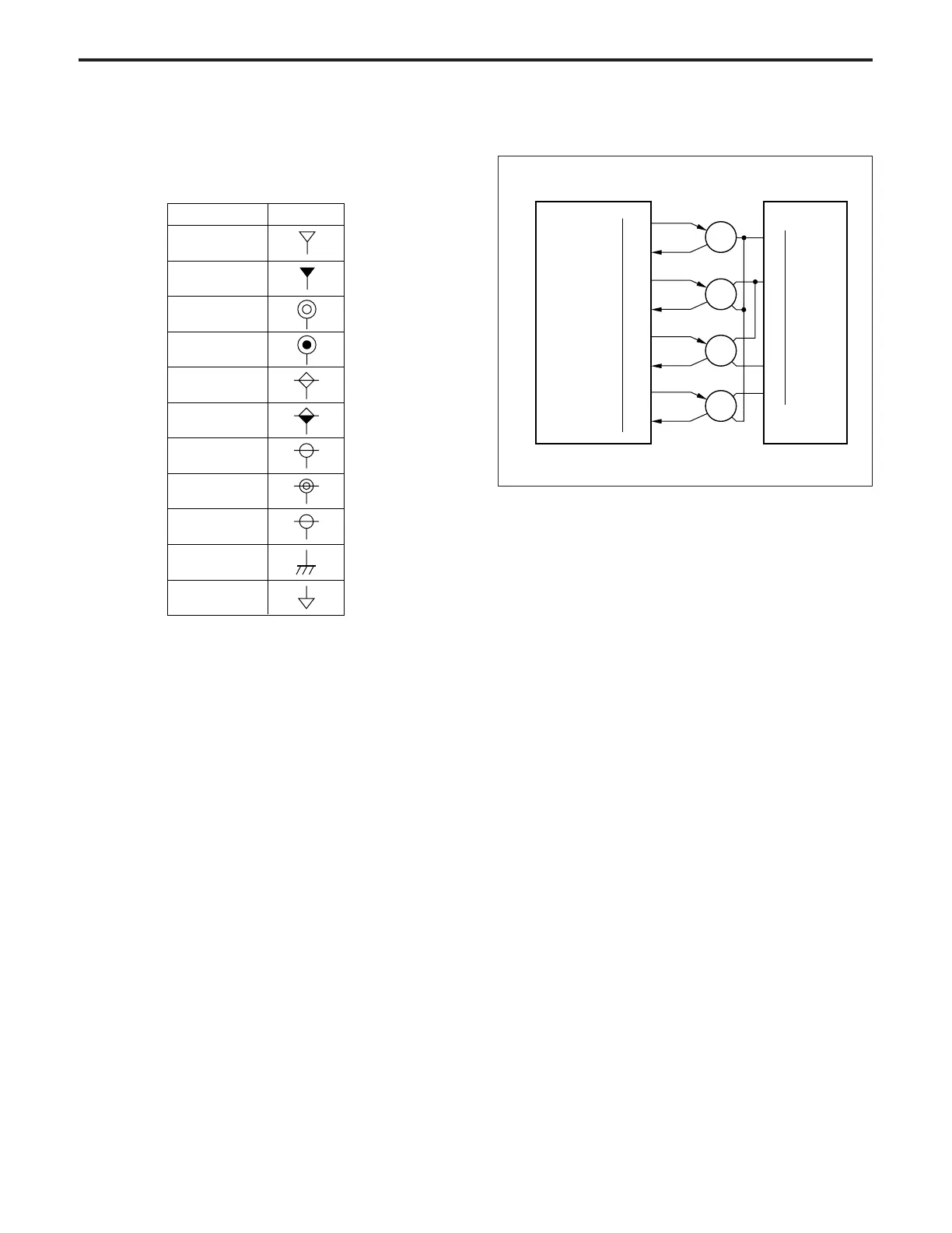
[3] Cooling Fan Control
PGND
24VDC
PGND
24VDC
99-4
99-3
78-7
2-2
DCPS
FM2 DRIVE
FM2 LD
FM11 H/L
FM11 LD
FM16 H/L
FM16 LD
FM22 H/L
FM22 LD
83-A1
83-B1
65-A4
65-A4
65-B10
65-B9
65-A7
65-A6
CB
FM2
FM11
FM16
FM22
The CB (control board) drives FM11 (polygon cooling fan),
FM22 (E-RDH cooling fan), FM16 (main body cooling fan) and
FM2 (optics cooling fan)
1. Operation
A 24 V DC motor is used for each cooling fan.
a. Operation of FM11
During idling: High speed rotation
During a copy operation: High speed rotation
b. Operation of FM22
During idling: Low speed rotation
During a copy operation: High speed rotation
c. Operation of FM16
During idling: Low speed rotation
During a copy operation: High speed rotation
d. Operation of FM2
ON only during a copy operation.
2. Signals
a. Intput signals
(1) FM11 LD (FM11 → CB)
This signal becomes [L] when FM11 reaches the set
speed.
40VDC (1)
40VDC (2)
24VDC (1)
24VDC (2)
12VDC
8VDC
5VDC (1)
5VDC (2)
– 5VDC
SGND
PGND
Output symbol
DC output voltages and corresponding symbols
2. Signals
a. Output signal
(1) RL DRIVE (CB → RL1)
Signal which controls RL1.
If an abnormality occurs in the main body, this signal
becomes [H], causing RL1, to go OFF.