2 - D - 3
DRIVE SECTION
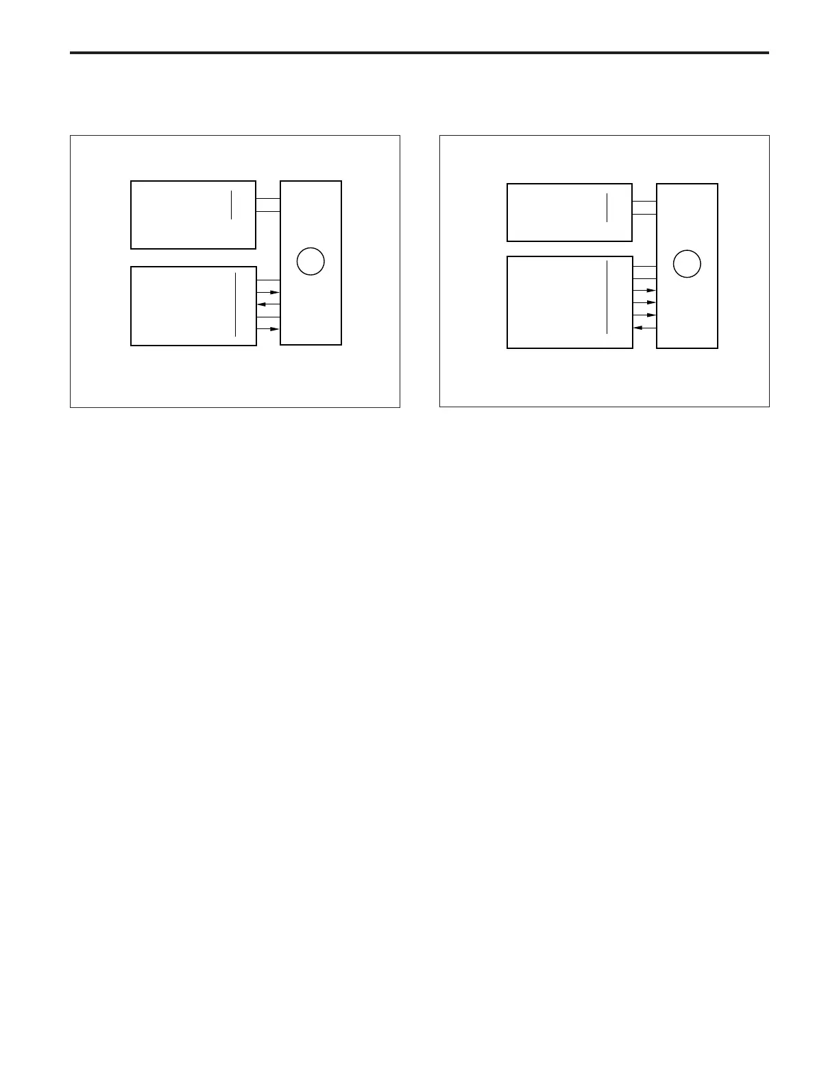
[4] M1 (main) Control [5] M4 (drum) Control
M4 (drum) is controlled by the CB (control board).
1. Operation
M4 is a 24 V drive DC motor which drives the drum and the
cleaning guide roller. M4 is PLL-controlled by reference
Signal and feedback signal from a speed sensor installed
inside M4 itself, maintaining it at a constant speed.
M4 goes ON when the Copy button is pressed, and goes
OFF again when the final copy has been exited.
2. Signals
a. Input signal
(1) M4PLL (M4 → CB)
[L] is output when M4 reaches the specified speed.
b. Output signals
(1) M4CONT (CB → M4)
M4 drive control signal
[L]: M4 ON
[H]: M4 OFF
(2) M4 H/L (CB → M4)
M4 rotational speed switchover signal
Normally [H]: 370 mm/sec
[L]: 185 mm/sec
(3) M4CLK (CB→M4)
Reference clock signal for controlling the speed of M4
24VDC
PGND
99-2
99-5
DCPS
5VDC
SGND
M4 CONT
M4 H/L
M4 CLK
M4 PLL
30-A8
30-A9
30-A10
30-B6
30-A11
30-A12
CB
M4
M1 (main) is controlled by the CB (control board).
1. Operation
M1 is a 40 V drive DC motor which drives the ADU paper
exit/conveyance, toner recycle, conveyance, 2nd paper
feed and fixing sections. M1 is PLL-controlled by feedback
signals from a speed sensor installed inside M1 itself,
maintaining it at a constant speed.
M1 goes ON when the
Start Print
is pressed, and goes OFF
again when the final copy has been exited.
During warm-up, M1 rotates, causing the fixing roller to
rotate.
2. Signals
a. Input signal
(1) M1 PLL (M1 → CB)
M1 rotation monitoring signal
[H]: Abnormal stop or rotation
[L]: Normal rotation
b. Output signals
(1) M1 CONT (CB → M1)
M1 drive control signal
[L]: M1 ON
[H]: M1 OFF
(2) M1 CLK (CB → M1)
M1 rotational speed control reference clock signal
40VDC
PGND
88-5
88-3
DCPS
5VDC
M1 CONT
M1 PLL
SGND
M1 CLK
30-A1
30-A3
30-A4
30-A5
30-A2
CB
M1
DRIVE SECTION-1