2 - D - 2
DRIVE SECTION
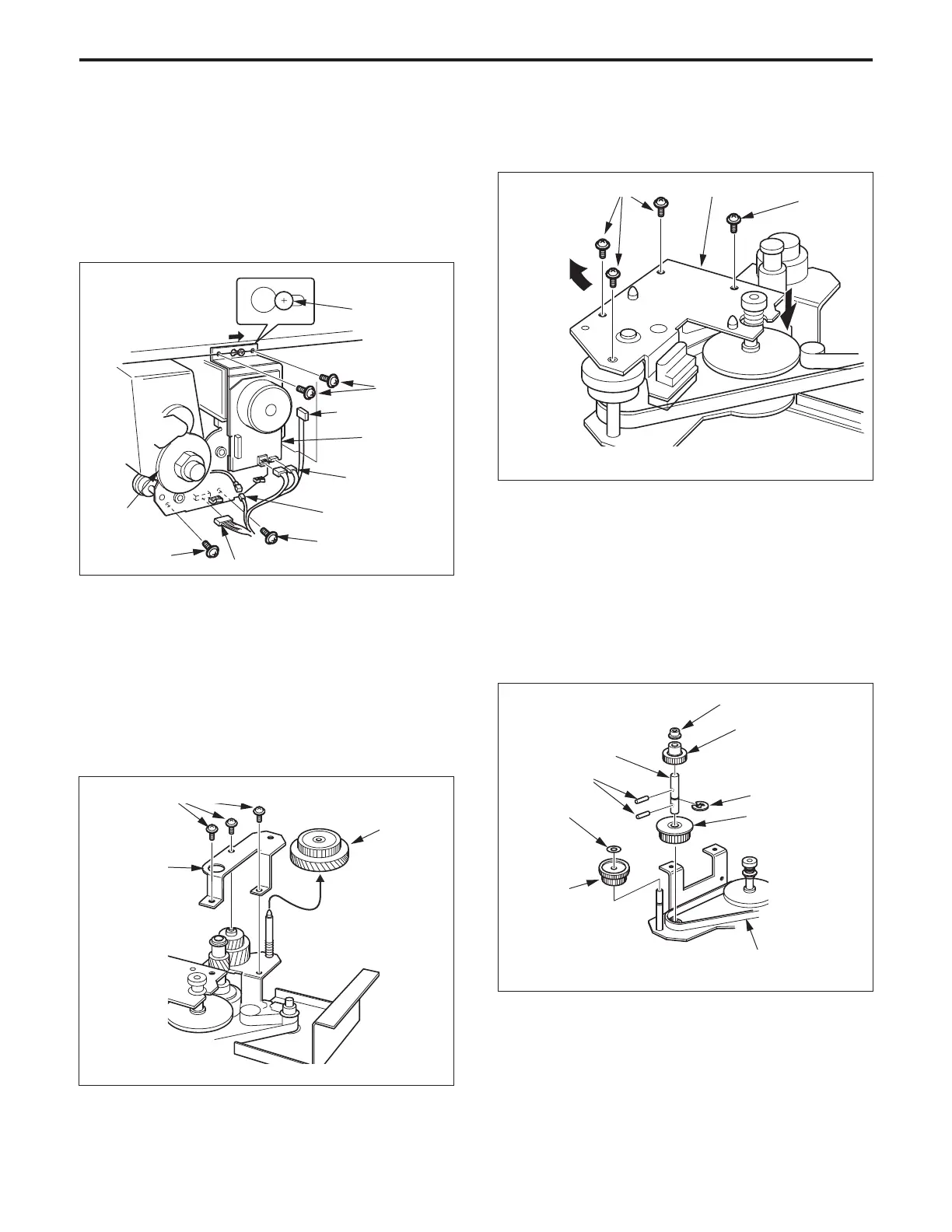
(4) Disconnect the relay connector and the four connec-
tors (CN16, 204, 205 and 324), then remove the cable
from the wiring clamp.
(5) Remove the four set screws, slide the main motor unit
to the right, then pull it forward and remove it.
Caution: DO NOT strike the main motor unit against the drum
drive gear when removing or re-installing it.
(4) Remove the four set screws, then remove the paper
feed drive plate.
Set screws
Paper feed drive plate
Set screw
Guide screw
Slotted hole
Set screw
Set screw
Drum
drive gear
Connector (CN324)
Relay
Connector
(6) Re-install the main motor unit in the opposite sequence
to removal.
2. Replacing the paper feed drive shaft and Fixing
input gear
a. Procedure
(1) Remove the main motor unit.
(2) Remove the three set screws, then remove the fixing
drive plate.
(3) Remove the fixing input gear.
Fixing drive
plate
Set screws
Fixing input
gear
(5) Remove the poly slider and the paper feed input gear.
Caution: Do not forget to re-install the poly slider when re-
installing the paper feed input gear.
(6) Remove the bearing and developing drive gear, then
pull out the pin remaining in the paper feed drive shaft.
(7) Remove the main body drive belt from the drive pulley.
(8) Remove the E ring from the paper feed drive shaft, then
remove the drive pulley.
(9) Remove the paper feed drive shaft, then pull out the pin
remaining in paper drive shaft.
Set screws
Connector (CN16)
Main motor
unit
Connector
(CN204, 205)
(10)Re-install the above parts in the opposite sequence to
removal.
Paper feed drive shaft
Developing drive gear
E ring
Main body drive belt
Drive pulley
Bearing
Pins
Poly slider
Paper feed
input gear
DRIVE SECTION-1