OTHER KINDS OF CONTROL
2 - T - 4
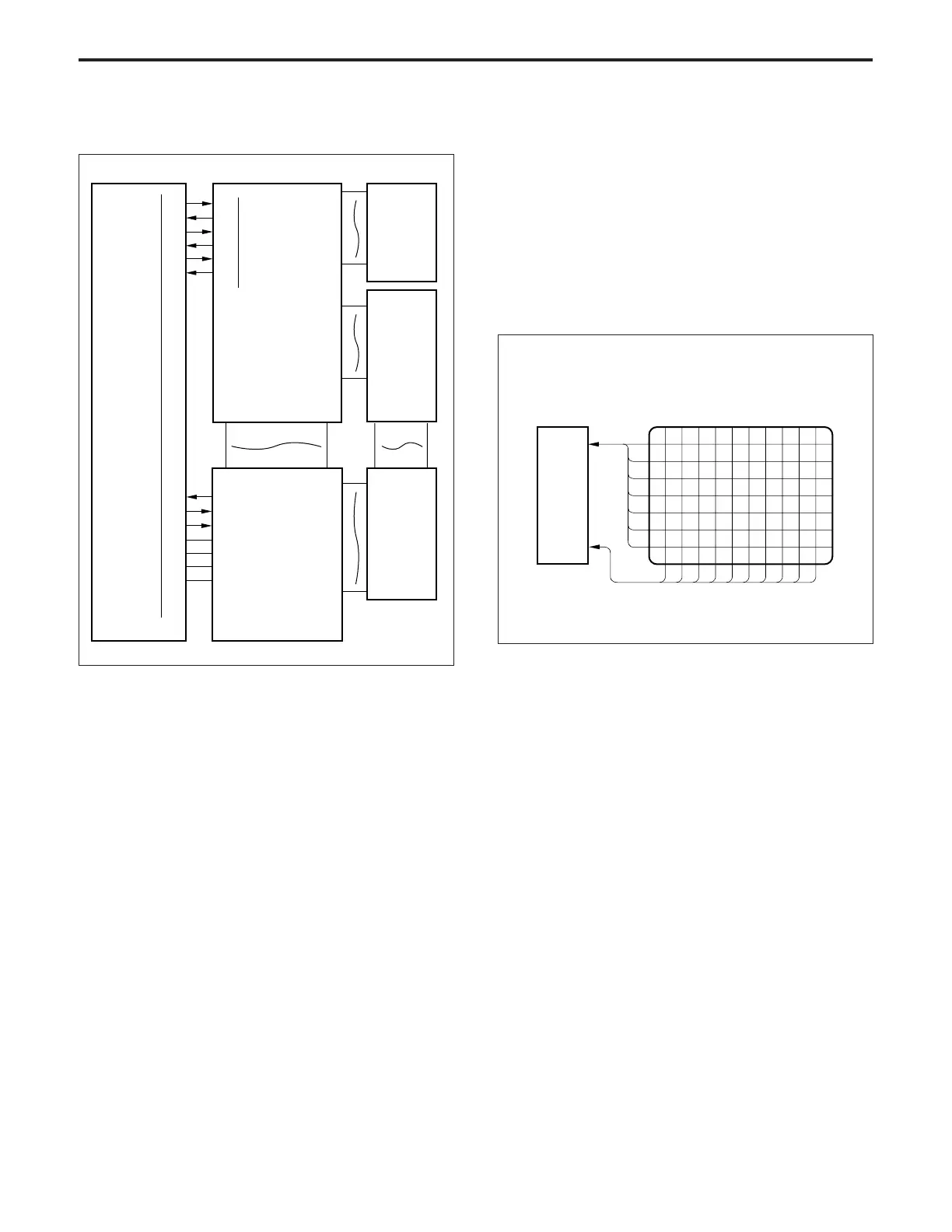
[4] Operation Panel Control
The operation panel consists of OB1 (operation board 1), OB2
(operation board 2) and the indicating board. On the indicating
board is mounted an LCD. The LCD has a backlight which is
powered by the indicating starter (LCD drive board), and touch
switches which are linked to the displayed contents.
Control of the operation panel is done by OB1 based on serial
data output from CB1 (main body control board).
1. Operation
a. LED ON operation
The LED and 7-segment LED on OB1 are turned ON and
OFF by several ICs (shift register/latch driver).
Each IC is turned ON and OFF according to serial data from
the CB.
b. LCD control
(1) LCD display operation
The LCD is driven by 4-bit parallel data from OB1.
(2) Backlight ON operation
The LCD has a backlight (cold cathode tube) to facili-
tate viewing. The backlight is driven by the indicating
starter, and controlled by OB1 via OB2.
(3) Touch switch control
The LCD has touch switches, enabling you to directly
select items indicated by the display. These touch
switches are controlled by OB1.
2. Signals
a. Input signals
(1) OB1 RXD (OB1 → CB1)
32-bit serial data which informs CB1 of the operation
status of OB1.
(2) OB1 CTS (OB1 → CB1)
Signal which indicates that data is being sent from OB1
to CB1.
When this signal is [H], CB1 stops sending the OB1
TXD signal.
(3) OB1 DSR (OB1 → CB1)
Received verification signal which is returned each
time one byte of data has been received, when OB1 is
receiving data from CB1.
(4) W.T. switch (OB2 → CB1)
Signal which indicates the operation status of the
weekly timer.
OB1 TXD
OB1 RTS
OB1 DTR
W.T SW
SD LE DRIVE
W.T LE DRIVE
SGND
SGND
8VDC
5VDC
3-A1
3-A2
3-A3
3-A4
3-A5
3-A6
413-5
413-6
413-7
413-8
3-B5
3-B6
3-B7
CB
10-1
10-2
10-3
10-4
10-5
10-6
OB1 RXD
OB1 CTS
OB1 DSR
OB1
221-1
221-2
221-3
221-4
215-1
215-2
215-4
OB2
OB3
INDICATING
BOARD
INDICATING
STARTER
OB1
LCD