2 - E - 11
READ SECTION
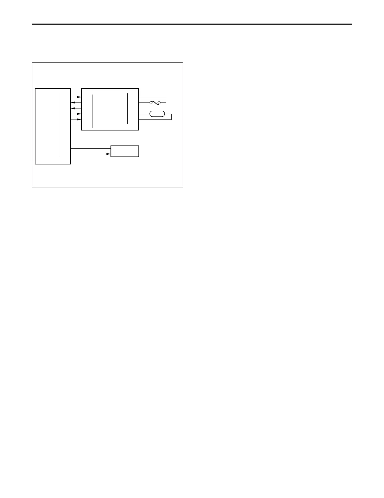
[5] Exposure Control
Power is supplied to L1 (exposure) from the CVR (exposure
lamp regulated power supply) and is controlled by the CB
(control board).
1. Operation
a. L1 light intensity control
The light intensity from L1 is determined by the output
voltage from the CVR circuit.
Rated output: 53 V DC
b. Protection from abnormality
* Hardware timer circuit
If L1 remains ON for about 40±18 seconds or longer for
some reason or other, the hardware timer in the CVR
operates, turning RL1 (main) OFF. As a result, power to
the AC loads including L1 is cut off.
* Temperature fuse
If L1 exceeds a certain temperature, f1 (optics tempera-
ture fuse) melts, cutting off the current to L1. (f1 melting
temperature: 121°C/250°F)
2. Signals
a. Input signals
(1) L1 FB (CVR → CB)
This signal informs the CB of the lit or unlit state of L1.
[L]: L1 ON
[H]: L1 OFF or broken
(2) RL1 INHIBIT (CVR → CB)
This signal turns OFF RL1 if an abnormality occurs in
the machine.
[L]: Abnormal
[H]: Normal
b. Output signal
(1) L1 CONT (CB → CVR)
This is a control signal which turns L1 ON and OFF.
[L]: L1 ON
[H]: L1 OFF
(2) CVR H/L (CB → L1)
CVR output voltage switching signal
[L]: Low output
[H]: High output
(3) L1 DRIVE1, 2 (CVR → L1)
L1 drive signal
(4) RL1 DRIVE (CB → CVR → RL1)
This signal controls RL1.
This signal becomes [H] and turns off RL1 if an abnor-
mality occurs in the machine.
29-2
29-3
29-1
29-4
29-5
29-6
L1 CONT
CVR H/L
24VDC
RL DRIVE
60-A2
60-A4
60-A1
60-A3
60-A10
60-A5
60-B10
60-B9
CB
L1 FB
RL INHIBIT
24VDC
SGND
AC (H)
AC (C)
L1 DRIVE 1
L1 DRIVE 2
380-1
380-3
385-3
385-1
CVR
RL1
L1
f1
AC (H)
AC (C)