2 - E - 10
READ SECTION
(8) M12 PLL (OPMDB → CB)
[L] is output when M4 reaches the specified speed.
(9) M12 MAG A/A' (M12 → OPMDB)
M12 MAG B/B' (M12 → OPMDB)
M12 MAG C/C' (M12 → OPMDB)
These are the output signals from the sensors (mag-
netic sensors) contained in M12. OPMDB detects the
position of the rotor of the motor by means of these
signals, and switches over the M12 DRIVE A to C
output.
(10)M12 FG (M12 → OPMDB)
This is a feedback signal from the rotational speed
sensor contained in M12. It is compared with the M12
CLK signal from the CB, and the output voltage ad-
justed so that the feedback signal becomes the same
as the M12 CLK signal, thus controlling the rotational
speed of M12.
b. Output signals
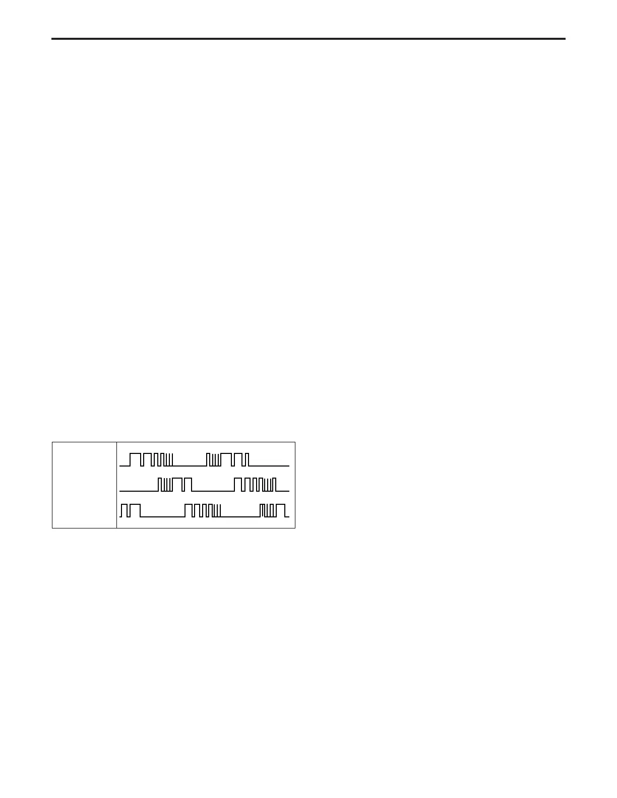
(1) M12 DRIVE A, B, C (OPMDB → M12)
This is the M12 drive signal. While M12 is rotating,
voltages are output sequentially from M12 DRIVE A to
C, and applied to M12.
The voltage from each output that is applied to M12
consists of the pulses shown below. The pulse width
of this output changes according to the rotation condi-
tion of M12, as shown in the figure, and as a result the
RMS value of the voltage applied to M12 changes,
causing the speed to be regulated.
(2) M12 CONT (CB → OPMDB)
M12 ON/OFF control signal
[L]: M12 ON
[H]: M12 OFF
(3) M12 CLK (CB → OPMDB)
M12 rotational speed control reference clock signal
(4) M12 F/R (CB → OPMDB)
Signal used to control the rotational direction of M12
[L]: Forward operation
[H]: Return operation
(5) M12 BRAKE (CB → OPMDB)
M12 brake control signal
(6) M12 NCR (CB → OPMDB)
M12 brake control signal
(7) M12 MODE 0, 1, 2 (CB → OPMDB)
M12 rotational speed control signal
Eight rotational speed modes are activated by combi-
nations of these three signals.
M12 DRIVE A
M12 DRIVE B
M12 DRIVE C