2 - I - 8
DEVELOPING UNIT
[9] Gradation Correction Control
12VDC
DRUM JAM CONT
SGND
γ LED CONT
γ/Dmax LED V ref
5-A12
5-B1
5-B4
5-B6
5-B7
5-B8
5-A11
CB
19-1
19-2
19-5
19-7
19-8
19-9
19-10
γ sig/MONI
DRUM JAM
TCSB
M3
5VDC
SGND
M4 CONT
M4 H/L
M4 CLK
M4 PLL
5VDC
SGND
M3 CONT
M3 CLK
M3 H/L
M3 LD
30-A8
30-A9
30-A10
30-B6
30-A11
30-A12
65-B3
65-B4
65-B5
65-B6
65-B7
65-B8
M4
24VDC
PGND
40VDC
PGND
99-2
99-5
88-4
88-2
DCPS
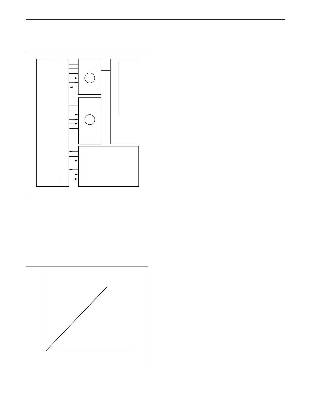
Gradation correction control is done by the TCSB (toner control
sensor board), M4 (drum), M3 (developing drive). These parts
are controlled by the CB.
1. Operation
The gradation characteristics of the toner density versus
exposure amount at the image forming section of each
machine is detected, and gradation correction processing
carried out in order to obtain a linear relation between the
original density and the copy density.
0 255
Copy density
Original density
(1) Contents of implementation
Exposure is performed while the laser exposure is
varied over several steps, and development is per-
formed at the sleeve speed resulting from Dmax cor-
rection.
Subsequently, each density is read by PD2 on the
TCSB, and the toner density and the gradation charac-
teristics of the toner density detected.
The gradation characteristics obtained here are used
as the correction values for the laser exposure amount.
(2) Implementation timing
a) When the power is switched ON
b) Every 3000 jobs (see *1)
*1: Can be changed with the 25 Mode software switch.
2. Signals
a. Input signal
(1) γ sig/MONI (TCSB → CB)
This is the output voltage from the gradation sensor
(PD2) on the TCSB and the monitor signal for the light
reflected from the drum surface (no toner).
The voltage impressed on the Dmax detection LED is
corrected (calibration) by γ/Dmax LED V ref.
Reference voltage: 9 V.
<Implementation timing>
To be performed before gradation correction.
(2) DRUM JAM (TCSB → CB)
This signal detects a jam caused by paper wrapping
around the drum. If it is more than 4.3 V, the CB judges
that a jam has occurred.
(3) M3 LD (M3 → CB)
[L] is output when M3 reaches the specified speed.
(4) M4 PLL (M4 → CB)
[L] is output when M4 reaches the specified speed.
b. Output signal
(1) γ LED CONT (CB → TCSB)
ON/OFF control signal for the gray scale detection
LED
[L]: LED ON
[H]: LED OFF
(2) γ/Dmax LED V ref (CB → TCSB)
The power supply line for the LED of PD2 on the TCSB.
The voltage value is adjusted so the γ MONI signal will
be 9 V DC.
(3) DRUM JAM CONT (CB → TCSB)
This signal controls the ON or OFF state of the wrap-
ping jam detection LED.
[L]: LED ON
[H]: LED OFF
(4) M3 CONT (CB → M3)
M1 drive control signal
[L]: M1 ON
[H]: M1 OFF