2 - F - 3
WRITE UNIT
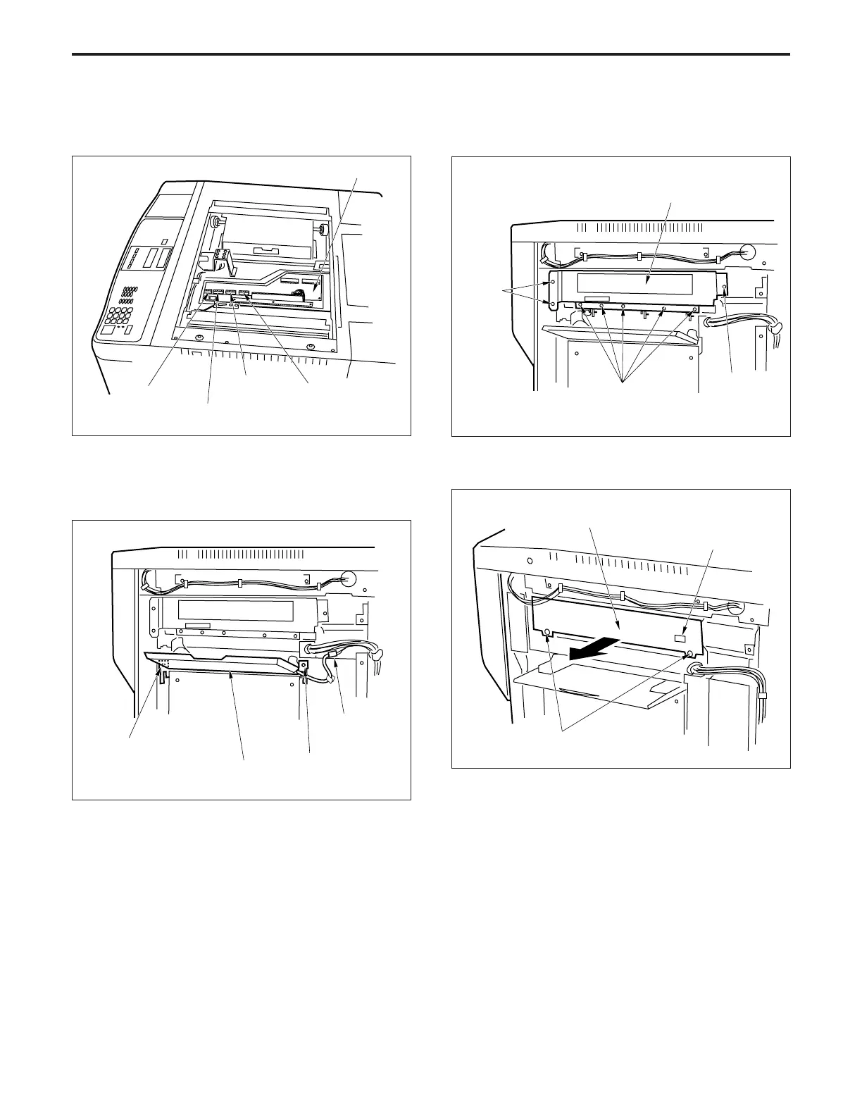
(4) Disconnect the four connectors (CN421, 422, 423 and
424) from the image processing board (IPB).
(5) Slacken the five set screws, then remove the upper
cover on the right side.
(6) Remove the relay connector and the two set screws,
then remove the bypass-feed base.
Image processing board (IPB)
Connector
(CN424)
Connector
(CN423)
Connector
(CN421)
Connector
(CN422)
Write unit cover
Set screws
Set screw
Set
screws
(7) Remove the eight set screws, then remove the write
unit cover.
(8) Disconnect the connector (CN95).
(9) Slacken the two set screws, then pull out the write unit.
Write unit
Connector
(CN95)
(10)Re-install the write unit in the opposite sequence to
removal.
Set screws
Set screw
Set screw
Relay
connector
Bypass-feed bese