2 - F - 5
WRITE UNIT
2. Signals
a. CB output signals
(1) M5 CONT (CB → PMDB)
This signal controls the ON/OFF state of M5.
L: M5 ON
H: M5 OFF
(2) M5 CLK (CB → PMDB)
This is a reference clock signal for PLL-controlling M5
in the PMDB.
(3) M5 BREAK (CB → PMDB)
Signal which brakes M5
L: Brake OFF
H: Brake ON
b. CB input signal
(1) M5 RDY (PMDB → CB)
This signal indicates the rotation condition of M5.
L: Specified rotational speed
H: If the specified speed has not been reached
c. PMDB input signal
(1) M5 MAG A/A' (M5 → PMDB)
(1) M5 MAG B/B' (M5 → PMDB)
(1) M5 MAG C/C' (M5 → PMDB)
These are output signals from the position sensors
(magnetic sensors) contained in M5. The PMDB
detects the position of the rotor of the motor by means
of these signals, and switches over the M12 DRIVE A
to C output.
d. PMDB output signal
(1) VMAG- (PMDB → M5)
GND line to the rotor position sensors (magnetic sen-
sors) contained in M5
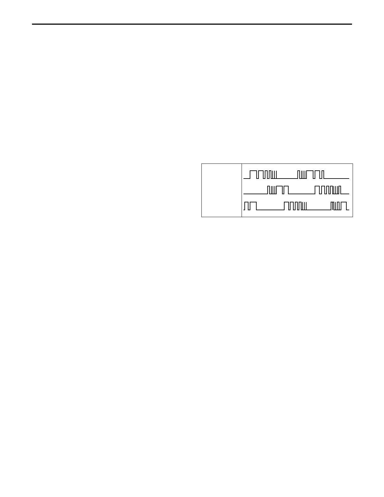
(2) M5 DRIVE A to C (PMDB → M5)
This is the drive output signal for M5. While M5 is
rotating, voltages are output sequentially from M12
DRIVE A to C, and applied to M5.
The voltage from each output that is applied to M5
consists of the pulses shown below. The pulse width
of this output changes according to the rotation condi-
tion of M5, as shown in the figure, and as a result the
RMS value of the voltage applied to M5 changes,
causing the speed to be regulated.
M5 DRIVE A
M5 DRIVE B
M5 DRIVE C