B
APEX1000 All-Purpose Edge QAM Software Version 2.4.x • Installation and Operation Manual
xiv
573408-001-a
AC/DC Power Redundancy ................................................................................................... 304
Removing a Power Supply or Filler Module.......................................................................... 304
Installing a Power Supply Module......................................................................................... 304
Installing a Power Supply Filler Module ................................................................................ 305
Appendix F ................................................................................................................................. 306
RS-232 Test Console Port ........................................................................................................... 306
Console Port Connection ...................................................................................................... 306
Establishing Communication with a PC ................................................................................ 306
Menu General Operations..................................................................................................... 307
Typical Scenarios................................................................................................................... 311
Glossary...................................................................................................................................... 312
Abbreviations and Acronyms....................................................................................................... 312
Figures
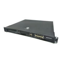
Figure 1-1 — APEX1000 front panel................................................................................................ 1
Figure 2-1 — APEX1000 dimensions............................................................................................... 6
Figure 2-2 — APEX1000 rear panel ............................................................................................... 10
Figure 3-1 — APEX1000 rack mounting ........................................................................................ 32
Figure 3-2 — Typical SFP transceiver installation/removal............................................................ 34
Figure 3-3 — APEX1000 front/rear panel I/O cable connectors .................................................... 35
Figure 5-1 — Administration window............................................................................................ 50
Figure 5-2 — System drop-down list as other user....................................................................... 53
Figure 5-3 — Set Password window............................................................................................. 54
Figure 6-1 — System Time Configuration ..................................................................................... 61
Figure 6-2 — Fast Ethernet Configuration..................................................................................... 64
Figure 6-3 — Traps Configuration.................................................................................................. 66
Figure 6-4 — Advanced Configuration........................................................................................... 67
Figure 6-5 — Redundancy with Heartbeat .................................................................................... 73
Figure 6-6 — 1:1 Chassis Redundancy Configuration ................................................................... 77
Figure 6-7 — DTA General Configuration ...................................................................................... 87
Figure 6-8 — DTA RF Port Configuration ...................................................................................... 89
Figure 6-9 — RADIUS Configuration ............................................................................................. 92
Figure 6-10 — EAS Configuration.................................................................................................. 95
Figure 6-11 — PSIP Configuration ................................................................................................. 97
Figure 6-12 — QAM Configuration ................................................................................................ 99
Figure 6-13 — QAM RF Port Configuration................................................................................. 102
 Loading...