Programming Model
http://www.motorola.com/computer/literature 3-47
3
Note In addition to the programmed address, the first 1Mbyte of Block
A also appears at $FFF00000 - $FFFFFFFF if the rom_a_rv bit
is set and the rom_b_rv bit is cleared.
Also note that the combination of ROM_A_BASE and
rom_a_siz should never be programmed such that ROM/Flash
Block A responds at the same address as the CSR, DRAM,
External Register Set, or any other slave on the PowerPC bus.
rom_a_64 indicates the width of ROM/Flash device/devices being used
for Block A. When rom_a_64 is cleared, Block A is 16 bits wide, where
each Falcon interfaces to 8 bits. When rom_a_64 is set, Block A is 64 bits
wide, where each Falcon interfaces to 32 bits. rom_a_64 matches the
value that was on the CKD2 pin at power-up reset. It cannot be changed by
software.
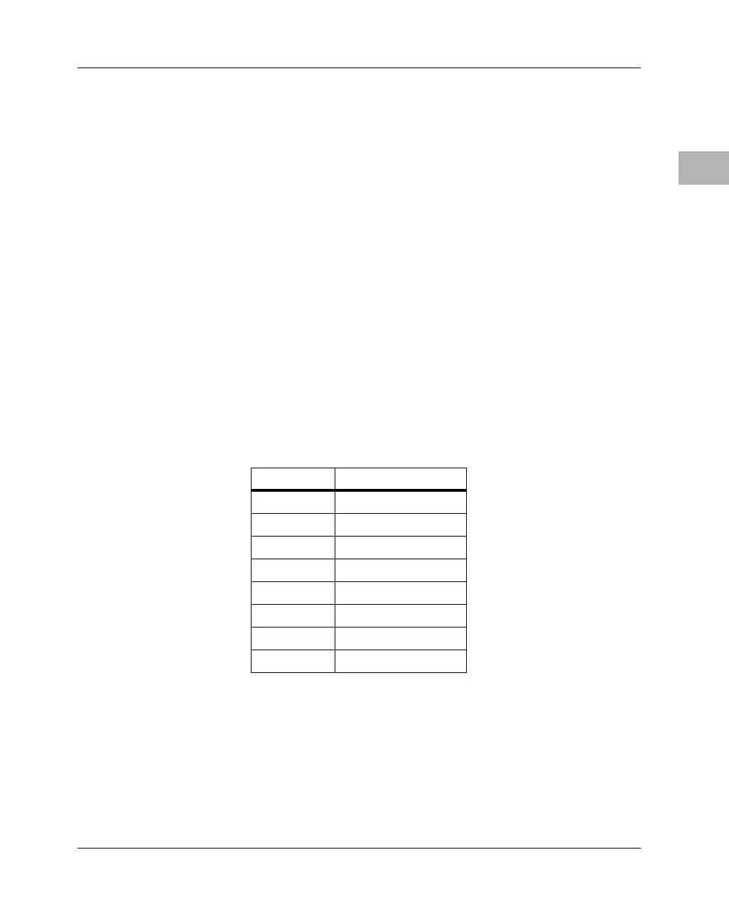
rom a siz The rom a siz control bits are the size of ROM/Flash for Block
A. They are encoded as shown in the following table.
Table 3-15. ROM/Flash Block A Size Encoding
rom a siz BLOCK SIZE
%000 1MB
%001 2MB
%010 4MB
%011 8MB
%100 16MB
%101 32MB
%110 64MB
%111 Reserved
 Loading...


