ISA Local Resource Bus
http://www.motorola.com/computer/literature 1-31
1
Note The direction and the polarity of the Z8536’s port pins are
software programmable.
Two Wire Serial (I
2
C) Bus Controller
The I
2
C bus controller controls communication with the DRAM DIMM
on-module EEPROM devices. The EEPROM devices contain the Serial
Presence Detect information (see section on System Memory for more
information). Refer to the PCF8584 data sheet for additional programming
information. The DIMM EEPROM addresses on the two wire serial bus
are shown in Table 1-20.
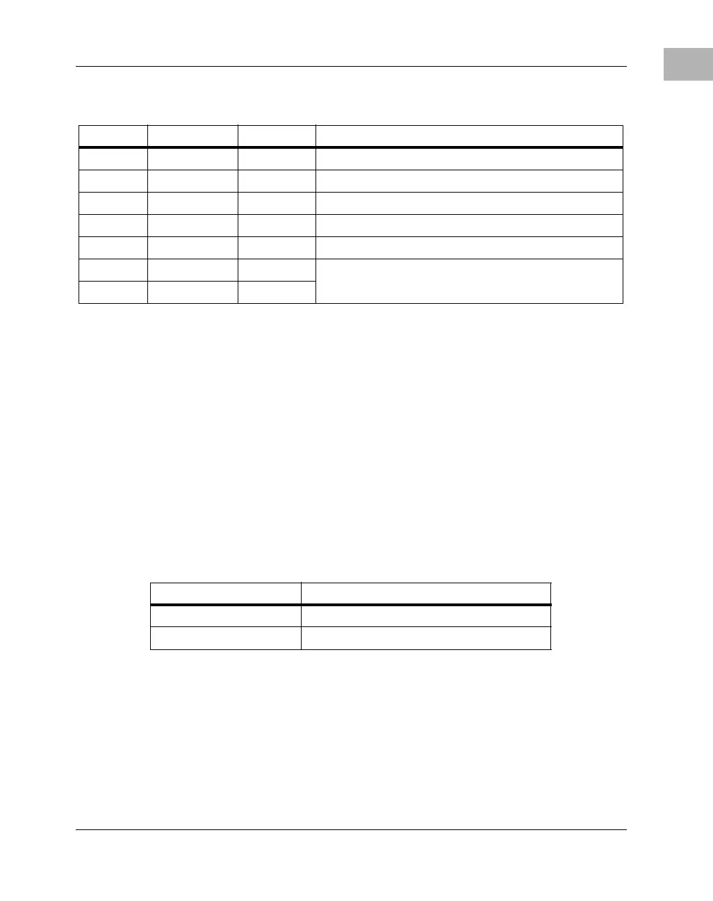
PB5 DTR4_ Output Port 4 Data Terminal Ready
PB6 Reserved I/O Reserved
PB7 ABORT_ Input Status of ABORT# signal
PC0 Reserved I/O Reserved
PC1 Reserved I/O Reserved
PC2 Reserved I/O Reserved
PC3 Reserved I/O
Table 1-19. I
2
C Controller Access Registers
PCI I/O Address Function
0000 0980 Operation Registers
0000 0981 Control/Status Register
Table 1-18. Z8536 CIO Port Pins Assignment (Continued)
Port Pin Signal Name Direction Descriptions
 Loading...


