4-14 Computer Group Literature Center Web Site
Programming Details
4
ROM/Flash Initialization
There are two methods used to inject code into the Flash in Bank A: (1) In-
circuit programming and (2) Loading it from the ROM/Flash Bank B. For
the second method, the hardware must direct the Falcon chipset to map the
FFF00000-FFFFFFFF address range to Bank B following a hard reset.
Bank A then can be programmed by code from Bank B.
Software can determine the mapping of the FFF00000-FFFFFFFF address
range by examining the rom_b_rv bit in the Falcon’s Rom B Base/Size
Register.
Determining PHB Type
The initialization software can determine the PCI Host Bridge (PHB) type
by reading its Device ID. To be backward compatible with the older
Genesis products which used the MPC105 as the PHB, the Raven defaults
the addresses of its CONADD register and its CONDAT register to
80000CF8 and 80000CFC, respectively.
The alternative method is to read the CPUTYPE from the Old CPU
Configuration Register which is located at offset 800h from the PCI I/O
Base Address.
Determining CPU Type
The SYID field in the System Configuration Register allows up to 256
types of CPU. This field is always FBh for the MTX.
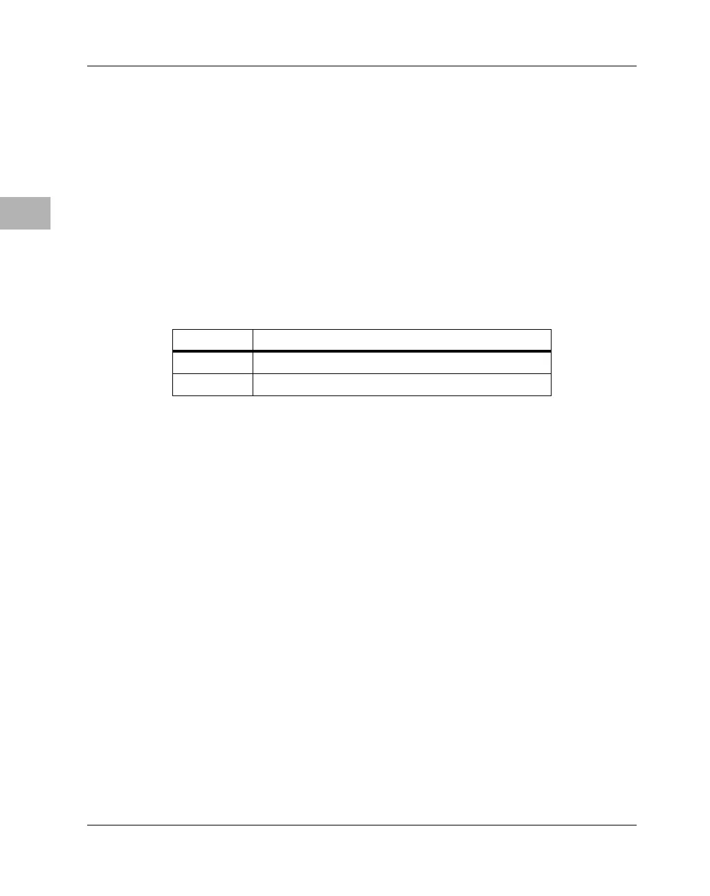
Table 4-7. ROM/FLASH Bank Default
rom_b_rv Default Mapping for FFF00000-FFFFFFFF
0 ROM/FLASH Bank A
1 ROM/FLASH Bank B
 Loading...


