Programming Model
http://www.motorola.com/computer/literature 1-5
1
The MTX series can be populated with two IEEE1386.1 PCI Mezzanine
Card (PMC) slots plus a 64-bit PCI slot, or with three 32-bit PCI slots. The
32-bit PCI slots support ATX standard I/O spacing. All slots use rear panel
I/O. The 64-bit PCI slot supports a horizontal PCI card via a custom riser
card.
DRAM memory is added via DIMM sockets, and the serial presence detect
(SPD) feature of the DIMM DRAMs is supported via the I
2
C bus
controller.
Programming Model
Memory Maps
The following sections describe the memory maps for the MTX series.
Processor Memory Maps
The Processor memory map is controlled by the Raven ASIC and the
Falcon chipset. The Raven ASIC and the Falcon chipset have flexible
programming Map Decoder registers to customize the system to fit many
different applications.
Default Processor Memory Map
After a reset, the Raven ASIC and the Falcon chipset provide the default
processor memory map as shown in the following table.
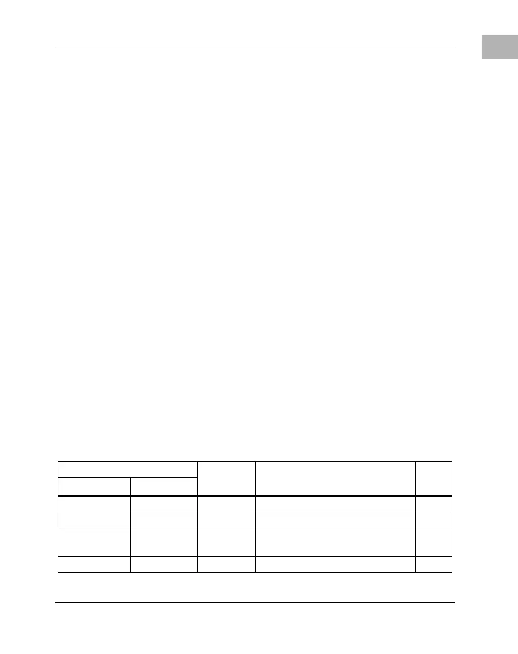
Table 1-2. Default Processor Memory Map
Processor Address Size Definition
Notes
Start End
0000 0000 7FFF FFFF 2G Not mapped
8000 0000 8001 FFFF 128K PCI/ISA I/O Space 1
8002 0000 FEF7 FFFF 2G - 16M -
640K
Not mapped
FEF8 0000 FEF8 FFFF 64K Falcon Registers
 Loading...


