2-4 Computer Group Literature Center Web Site
Raven PCI Host Bridge & Multi-Processor Interrupt Controller
2
Functional Description
PPC Bus Interface
The PPC Bus Interface is designed to be coupled directly to up to two PPC
microprocessors as well as a memory/cache subsystem. It uses a subset of
the capabilities of the PPC bus protocol.
PPC Map Decoders
The Raven address decoders have been designed to be as flexible as
possible to provide a wide range of addressing possibilities. There are five
address map decoders in the Raven which determine the PPC bus
addresses to which the Raven will respond: the PPC Register File Decoder,
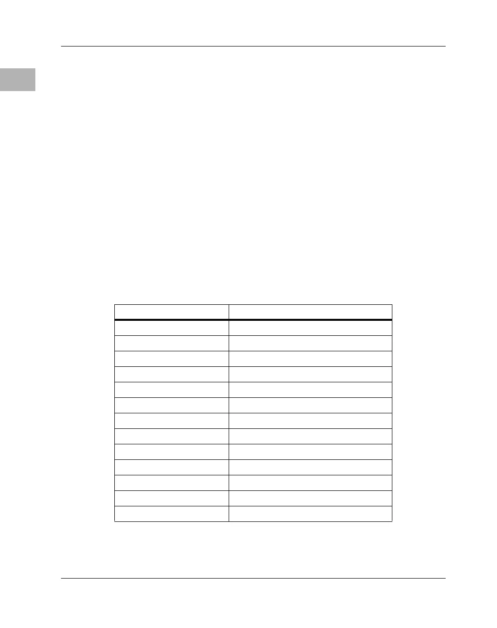
and four programmable decoders. Table 2-1 shows a typical CHRP
compliant memory map. (Another similar map is shown in Table 1-3.)
Table 2-1. CHRP Compliant Memory Map
PPC Address Function
$00000000-$7FFFFFFF System Memory (2G)
$80000000-$FCFFFFFF PCI Memory (2G - 48M)
$FD000000-$FDFFFFFFF ISA Memory (16M)
$FE000000-$FE7FFFFF Discontiguous PCI IO (8M)
$FE800000-$FEBFFFFF Contiguous PCI IO (4M)
$FEC00000-$FEF7FFFF reserved (3.5M)
$FEF80000-$FEF8FFFF Falcon 0 Registers (64K)
$FEF90000-$FEF9FFFF Falcon 1 Registers (64K)
$FEFA0000-$FEFAFFFF Falcon 2 Registers (64K)
$FEFB0000-$FEFBFFFF Falcon 3 Registers (64K)
$FEFC0000-$FEFEFFFF reserved (192K)
$FEFF0000-$FEFFFFFF Raven Registers (64K) (EXT00 => 0)
$FF000000-$FFFFFFFF System ROM/Flash (16MB)
 Loading...


