3-50 Computer Group Literature Center Web Site
Falcon ECC Memory Controller Chip Set
3
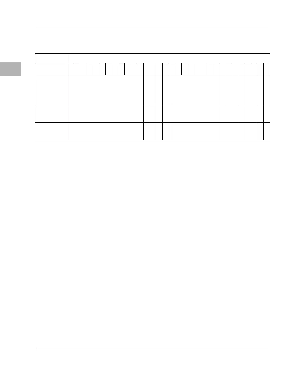
ROM B Base/Size Register
ROM B BASE These control bits define the base address for ROM/Flash
Block B. ROM B BASE bits 0-11 correspond to PowerPC 60x address bits
0 - 11 respectively. For larger ROM/Flash sizes, the lower significant bits
of ROM B BASE are ignored. This means that the block’s base address
will always appear at an even multiple of its size. ROM B BASE is
initialized to $FF4 at power-up or local bus reset.
Note In addition to the programmed address, the first 1MB of Block B
also appears at $FFF00000 - $FFFFFFFF if the rom_b_rv bit is
set.
Also note that the combination of ROM_B_BASE and
rom_b_siz should never be programmed such that ROM/Flash
Block B responds at the same address as the CSR, DRAM,
External Register Set, or any other slave on the PowerPC bus.
rom_b_64 indicates the width of ROM/Flash device/devices being used
for Block B. When rom_b_64 is cleared, Block B is 16 bits wide, where
each Falcon interfaces to 8 bits. When rom_b_64 is set, Block B is 64 bits
wide, where each Falcon interfaces to 32 bits. rom_b_64 matches the
inverse of the value that was on the CKD3 pin at power-up reset. It cannot
be changed by software.
Address
$FEF80058
Bit
0
1
2
3
4
5
6
7
8
9
10
11
12
13
14
15
16
17
18
19
20
21
22
23
24
25
26
27
28
29
30
31
Name
ROM B BASE
rom_b_64
rom b siz0
rom b siz1
rom b siz2
0
0
0
0
0
rom_b_rv
rom b en
rom b we
Operation
READ/WRITE
R
R/W
R/W
R/W
READ ZERO
R
R
R
R
R
R/W
R/W
R/W
Reset
$FF4 PL
V P
0 PL
0 PL
0 PL
X
X
X
X
X
X
V P
0 PL
0 PL
 Loading...


