SHOP MANUAL MT26/31 - 08.2006 SHOP MANUAL MT26/31 - 08.2006
SHOP MANUAL MT26/31 - 08.2006 SHOP MANUAL MT26/31 - 08.2006
TRANSMISSION
Ch 2 page 134 Ch 2 page 135
TRANSMISSION
TRANSMISSION
Ch 2 page 134 Ch 2 page 135
TRANSMISSION
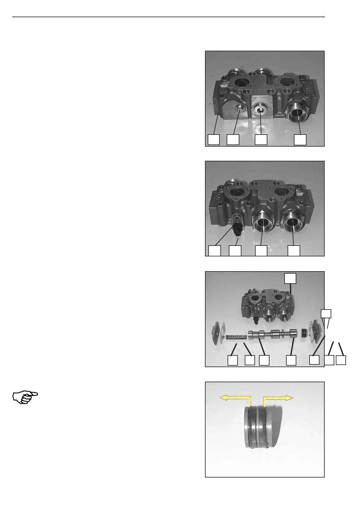
Figure 109
Figure 110
Install components according to the Figure on the left:
1 = Selector housing
2 = Cover
3 = Gasket
4 = Compression spring
5 = Spool
6 = Spool
7 = Grooved rings (2x)
8 = Gasket
9 = Cover (with pressure port)
Install grooved rings 7, with the sealing edge
always showing in Arrow direction,
see Figure 110 !
1
3
4
2
5
6
7
2
3
Figure 108
Pre-assemble and mount Retarder:
Install components according to Figure 107 and 108.
1 = Selector housing
2 = Screw plug (M14x1,5, Torque limit 35 Nm
3 = Screw plug (M26x1,5, Torque limit 80 Nm
4 = Screw-in sleeve
5 = Temperature sensor Torque limit 35 Nm
6 = Screw plug (M14x1,5, Torque limit 35 Nm
Equip screw plugs (2, 3 and 6) as well as temperature sen
-
sor (5) with new O-rings !
Wet thread of the screw-in sleeves (4) with Loctite (Type-
No. 262) !
Figure 107
1
3
4
2
5
6
4
4