TRANSMISSION
Ch 2 page 224 Ch 2 page 225
TRANSMISSION
SHOP MANUAL MT26/31 - 08.2006 SHOP MANUAL MT26/31 - 08.2006
TRANSMISSION
Ch 2 page 224 Ch 2 page 225
TRANSMISSION
SHOP MANUAL MT26/31 - 08.2006 SHOP MANUAL MT26/31 - 08.2006
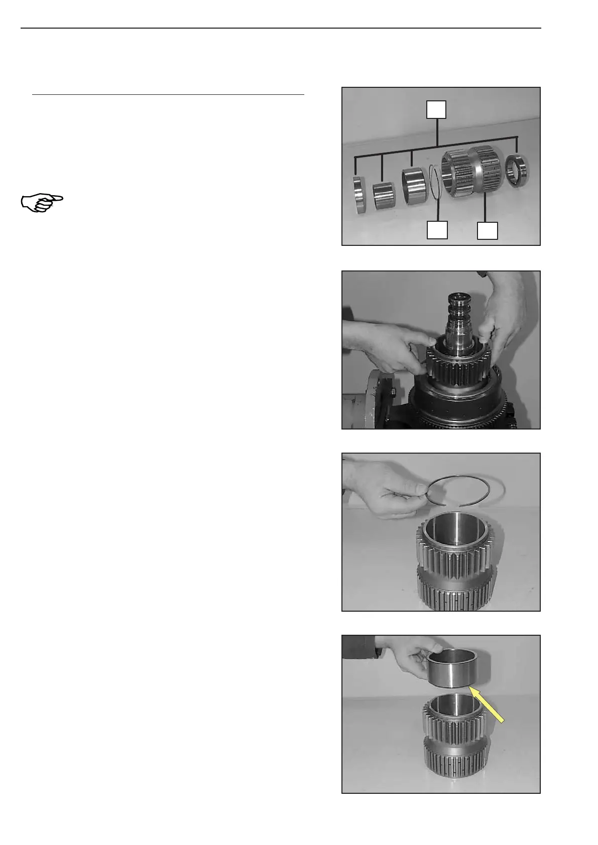
Figure 353
Figure 356
Figure 355
Figure 354
Pre-assemble and install spur gearK1 (Figure 353 ... 360):
The figure on the left shows the components of spur gear K1.
1 = Ball bearing (compl.)
2 = Snap ring
3 = Spur gear
Prior to the installation of the components,
radially align plate pack by means of spur
gear and center it, see Figure 354!
Install snap ring.
Introduce bush with the end face-side collar (arrow) facing the
snap ring.
Install snap ring.
1
2
3