SHOP MANUAL MT26/31 - 08.2006 SHOP MANUAL MT26/31 - 08.2006
SHOP MANUAL MT26/31 - 08.2006 SHOP MANUAL MT26/31 - 08.2006
TRANSMISSION
Ch 2 page 276 Ch 2 page 277
TRANSMISSION
TRANSMISSION
Ch 2 page 276 Ch 2 page 277
TRANSMISSION
Figure 530
Figure 533
Figure 532
Figure 531
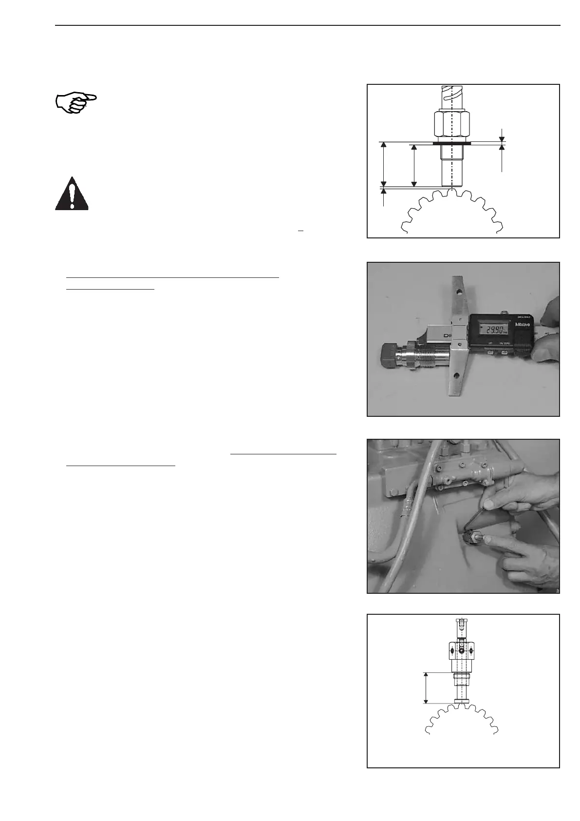
The following figures describe the assembly or
setting of the inductive transmitter n-engine (606)!
The assembly of the inductive transmitter
n-turbine (612) and n – central gear train (608)
must be accordingly carried out!
Pay attention to different setting dimension ,,X“:
Induct. transmitter n-engine(606) X =0,5
+ 0,3
mm
Induct. transmitter n-turbine(612) X =0,5
+ 0,3
mm
Induct. transmitter n-centr.gear train
(608) X = 0,3 + 0,1 mm
(S) Plug gauge 504177
Radially rotate counting disc until one tooth tip is central to the
inductive transmitter bore.
Screw in plug gauge until contact is obtained.
Position anvil on tooth tip until contact is obtained and lock it by
means of set screw (Figure 532 and 533).
(S) Plug gauge 504177
Set measure X by means of adjusting disc (n)
(Figure 531 ... 536):
Determine measure I from the contact face to the screw-in face
on the inductive transmitter.
Measure I e.g. .......................................... 30,00 mm