SHOP MANUAL MT26/31 - 08.2006 SHOP MANUAL MT26/31 - 08.2006
SHOP MANUAL MT26/31 - 08.2006 SHOP MANUAL MT26/31 - 08.2006
TRANSMISSION
Ch 2 page 278 Ch 2 page 279
TRANSMISSION
TRANSMISSION
Ch 2 page 278 Ch 2 page 279
TRANSMISSION
Figure 534
Figure 536
Figure 535
Screw out plug gauge and determine measure II
(also see Figure 533).
Measure II e.g. ........................................ 30,10 mm
Install inductive transmitter n - engine (14), see arrow !
Torque limit .................... M
A
= 30 Nm
Accordingly set and install inductive
transmitter n-turbine (6)and n-central gear
train (39)!
Pay attention to different setting measures!
Installation position of the single inductive
(See also chapter 2.2 ,Testing & Adjusting)
Line up suitable adjusting disc(s) and wet thread (arrow) with
(type-no. 574).
CALCULATION EXAMPLE “ M
1
“:
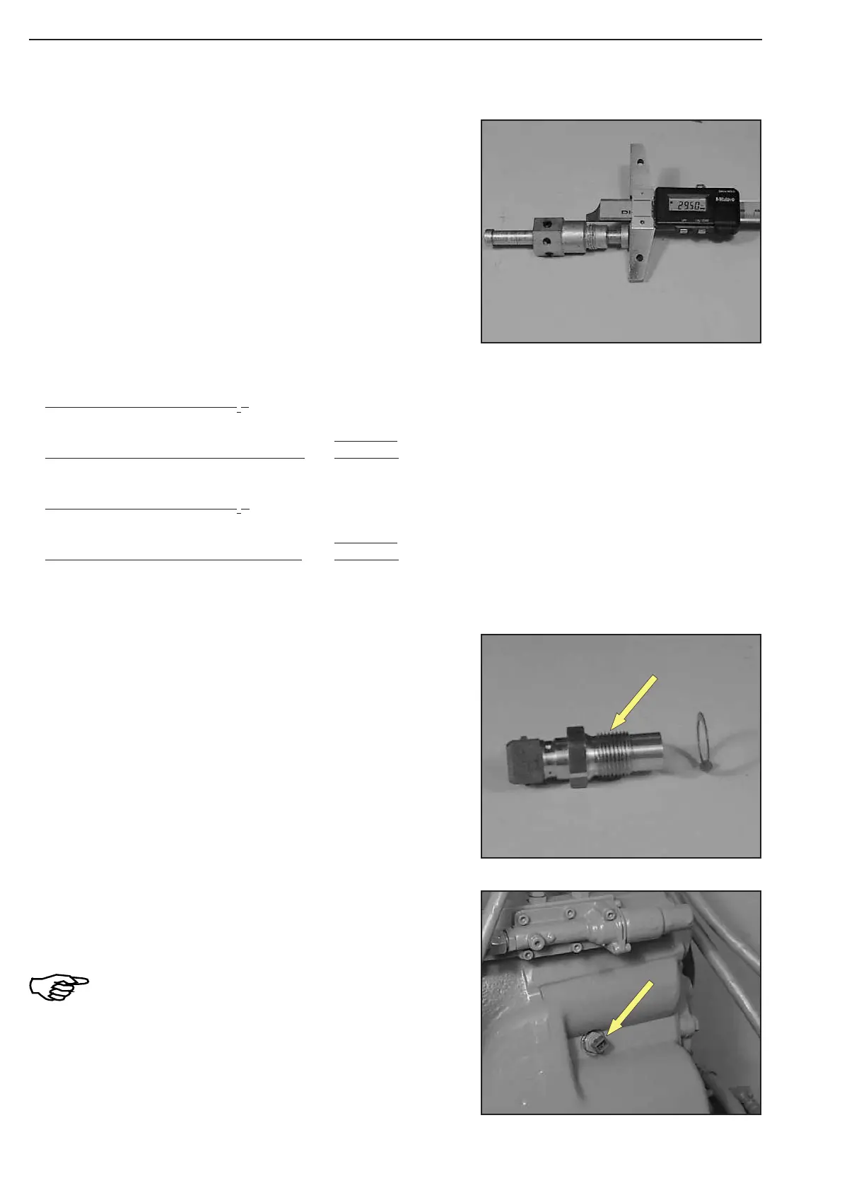
Measure II e.g. ....................................... 30,10 mm
Measure X (0,5
+ 0,3
mm) ................. e.g.. − 0,60 mm
Gives installation measure A = 29,50 mm
CALCULATION EXAMPLE “ M
2
“:
Measure I e.g. ........................................ 30,00 mm
Installation measure A e.g. .................... − 29,50 mm
Gives adjusting disc(s) s = 0,50 mm