SHOP MANUAL MT26/31 - 08.2006 SHOP MANUAL MT26/31 - 08.2006
SHOP MANUAL MT26/31 - 08.2006 SHOP MANUAL MT26/31 - 08.2006
TRANSMISSION
Ch 2 page 290 Ch 2 page 291
TRANSMISSION
TRANSMISSION
Ch 2 page 290 Ch 2 page 291
TRANSMISSION
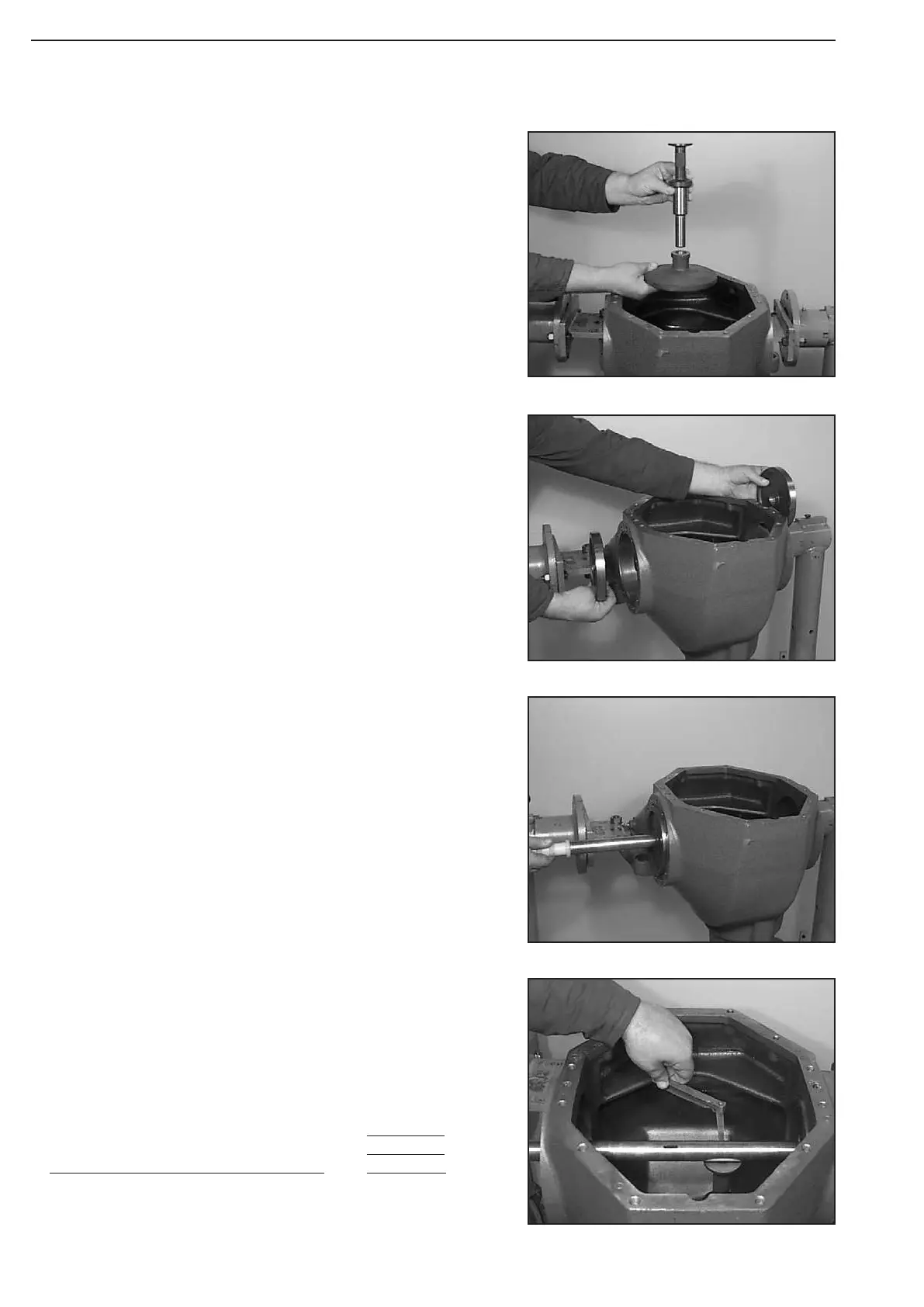
Figure 575
Figure 578
Figure 577
Figure 576
Insert stop disk (2) and plug gauge (1) into the bearing bore (drive
pinion).
(S) Stop disk 505157
(S) Plug gauge 505156
Determine Dimension by means of feeler gauge.
Dimension b e.g. .................................. 2,50 mm
EXAMPLE „ O
1
“:
Dimension a (stop disk + plug gauge) 224,00 mm
Dimension b e.g. .................................. +
2,50 mm
Dimension c (1/2 Æ meassuring shaft) +
15,00 mm
Gives Dimension X e.g. = 241,50 mm
Introduce measuring shaft (4).
(S) Measuring shaft 505158
Introduce both fitting pieces (3) into the bearing bores (differential
bearing).
(S) Fitting pieces 504728