EasyManuals Logo

Muratec F-525 User Manual

Muratec F-525
383 pages
To Next Page IconTo Next Page
To Previous Page IconTo Previous Page
Page #66 background imageLoading...
Page #66 background image
2-13
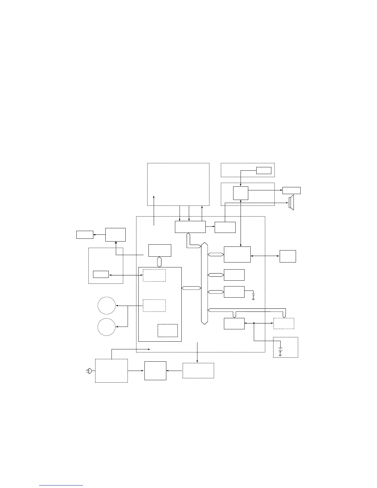
2.5 Main Control PCB
The main control PCB controls the operations of all machine functions.
Jumper JP1 on the main control PCB is used for battery back up of the SRAM. All user programmed
data and internal memory switch settings are held in SRAM. Removing JP1 will initialize the SRAM.
If the power is turned off, the battery will provide up to five years of back up when fully charged.
Note: JP1 should remain in the “ON” position at all times.
Memory (FLASH MEMORY, SRAM, SDRAM)
FLASH MEMORY --- The FLASH MEMORY contains all program instructions for unit operation.
SRAM --- The SRAM, which is backed-up by a lithium battery is used to store user programmed
information.
SDRAM --- The SDRAM is used for buffer, which is backed-up by a battery is used to store memo-
rized documents.
Note: Turning parameters for Color(R,G,B) and Gray mode are stored in the EEPROM(IC42). When
the PCB MAIN is replaced, the EEPROM on malfunction PCB should be replaced to the new
PCB.
FBS
MOTOR
ADF
MOTOR
NCU PCB
TONE RXA TXA
DISPLAY
KEY
PANEL
CPU
PANAEL PCB A
PANAEL PCB B
MODEM
MONITOR
CONTROL
CPU
USB
SRAM
SDRAM SDRAM
Ni-MH
H.V.POWER
SUPPLY UNIT
AC
PRINTER
CONTROL
MOTOR
CONTROL
IMAGE
PROCESS
CCD
SDRAM
INVERTERCCFL
CCD PCB
+24V,
+24V,
+5V,+3.3V
MAIN CONTROL PCB
CENECTOR-B PCB
Extention Memory
Lithium
+24V
+24V,+12V,AREF
FLASH
MEMORY
POWER SUPPLY
UNIT
PRINTER
UNIT
MFP
ENGINE
Main control PCB block diagram

Table of Contents

Other manuals for Muratec F-525

Questions and Answers:

Question and Answer IconNeed help?

Do you have a question about the Muratec F-525 and is the answer not in the manual?

Muratec F-525 Specifications

General IconGeneral
BrandMuratec
ModelF-525
CategoryAll in One Printer
LanguageEnglish

Related product manuals