2-15
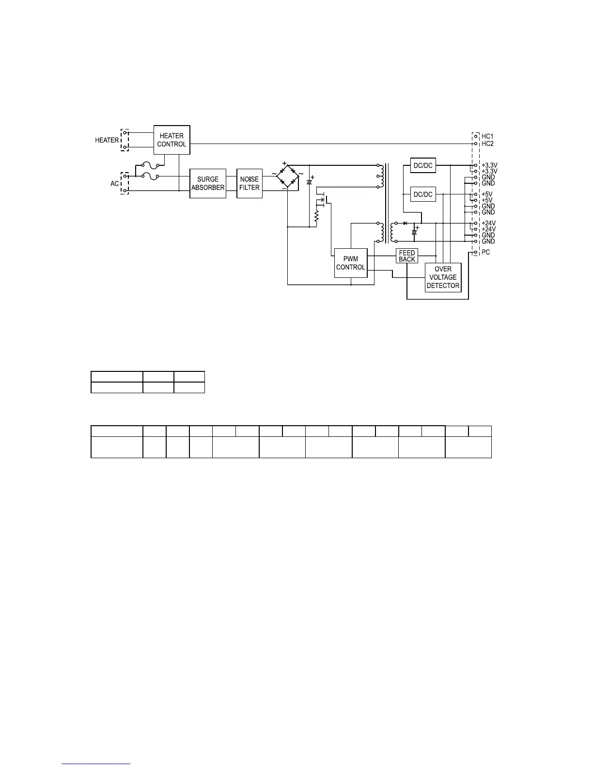
2.7 Power Supply Unit (PSU)
The power supply unit receives the input line voltage and currents it to output voltages of +3.3DVC,
+5 VDC and +24 VDC.
The heater circuit controls output voltage to the fuser heater according to instructions received from
the heater control circuit.
If an over-current is sensed in the secondary circuit, power is interrupted.
The power supply unit has two output connectors.
The following table shows the connector outputs:
CN101 -- to the Fuser Heater
Pin No. 1 2
Output L N
CN2 -- to the Main Control PCB.
Pin No. 1 2 3 4 5 6 7 8 9 10 11 12 13 14 15
Output
voltage
PC HC2 HC1 +5V SG +3.3V SG +24V PG