3-5
Machine Parameter 000 ~ 006 — Factory use only
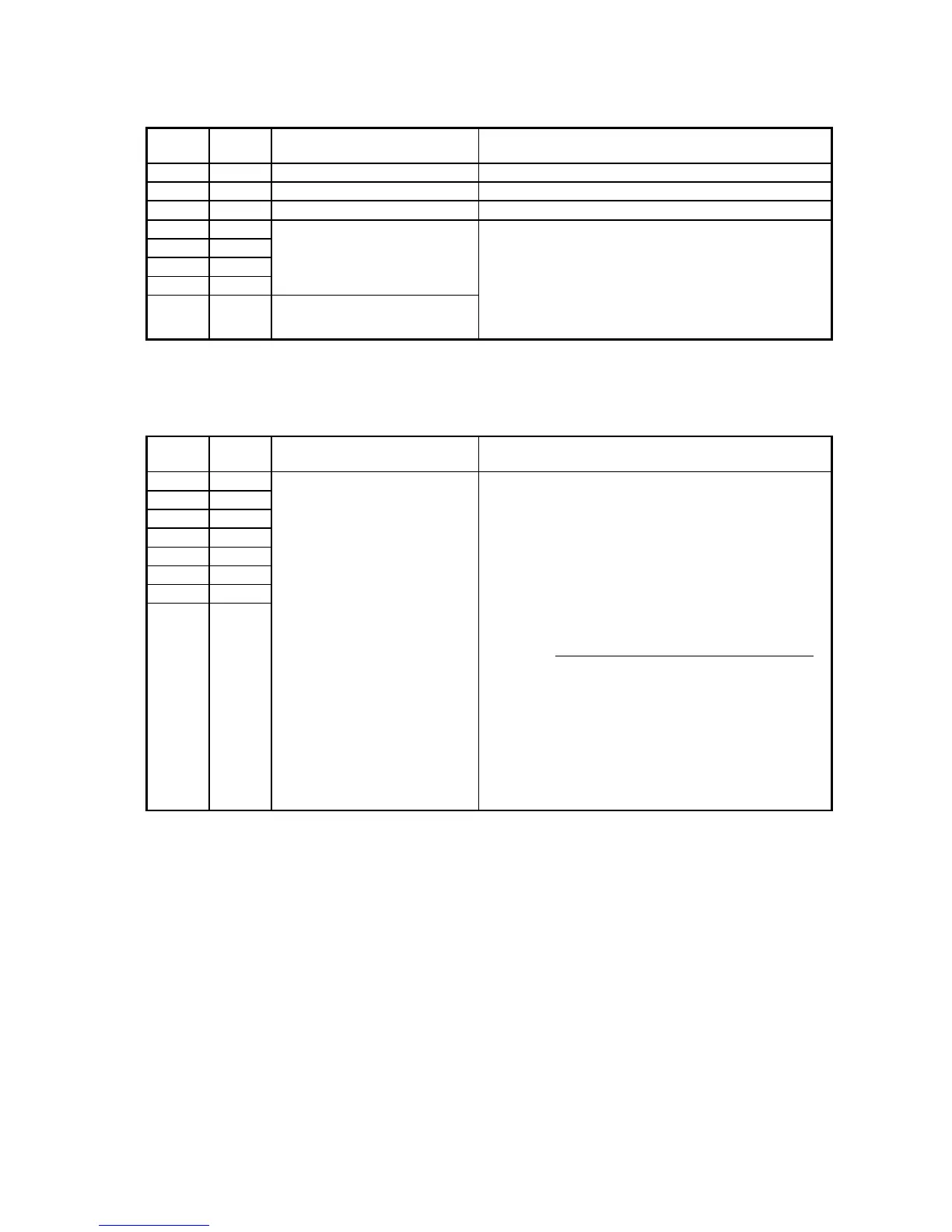
Machine Parameter 007
Switch Initial
Setting
Adjust Usage/Comments
7 0 Factory use only
6 0 Factory use only
5 0 Factory use only
4 0 DRAM capacity indication
on the Main PCB
This switch indicates the DRAM capacity.
(This switch is read only, do not set any character)
You can see the memory capacity by how many “1”
is indicated on the LCD. One “1” means 8MB.
For example, if three “1” are indicated,
i.e. “00000111”, the DRAM capacity is
8MB x 3 = 24MB.
3 0
2 0
1 0
0 0 DRAM capacity indication
on the Main PCB
Machine Parameter 008 and 009 — Factory use only
Machine Parameter 010
Switch Initial
Setting
Adjust Usage/Comments
7 0 ADF scanner registration
adjustment (Horizontal)
Adjusts the start point to
scan the document.
The plus setting increases
the left margin and the minus
setting decreases it.
1 step = 2 / 600 dpi
(0.0847 mm)
Note: These values
are factory set and should
not be adjusted unless
instructed by a Muratec
technical representative.
Switch 76543210 Settings
127 steps 01111111 +10.76 mm
:
00100000 +2.71 mm
:
00010000 +1.36 mm
:
00001000 +0.68mm
:
00000000 0 mm Initial setting
:
10001000 -0.68 mm
:
10010000 -1.36 mm
:
10100000 -2.71 mm
:
-127steps 11111111 -10.76 mm
6 0
5 0
4 0
3 0
2 0
1 0
0 0