104
n Adjusting Crease Depth
1. Objective
Adjusting the depth of the crease.
• Removing the Creaser Assembly
\See page 70
NOTE :
• You need to adjust the sensor plate after
installing the creaser assembly.
• You need to adjust the creaser perpendicu-
larity and creaser calibration after adjusting
the sensor plate.
• Creaser Sensor Plate Adjustment
\See page 118
• Creaser Perpendicularity Adjustment
\See page 108
• Creaser Calibration
\See page 100
2. How to make adjustments
NOTE :
• A test sheet may be creased by inserting it in
the creaser gap and manually rotating the
creaser unit pulley.
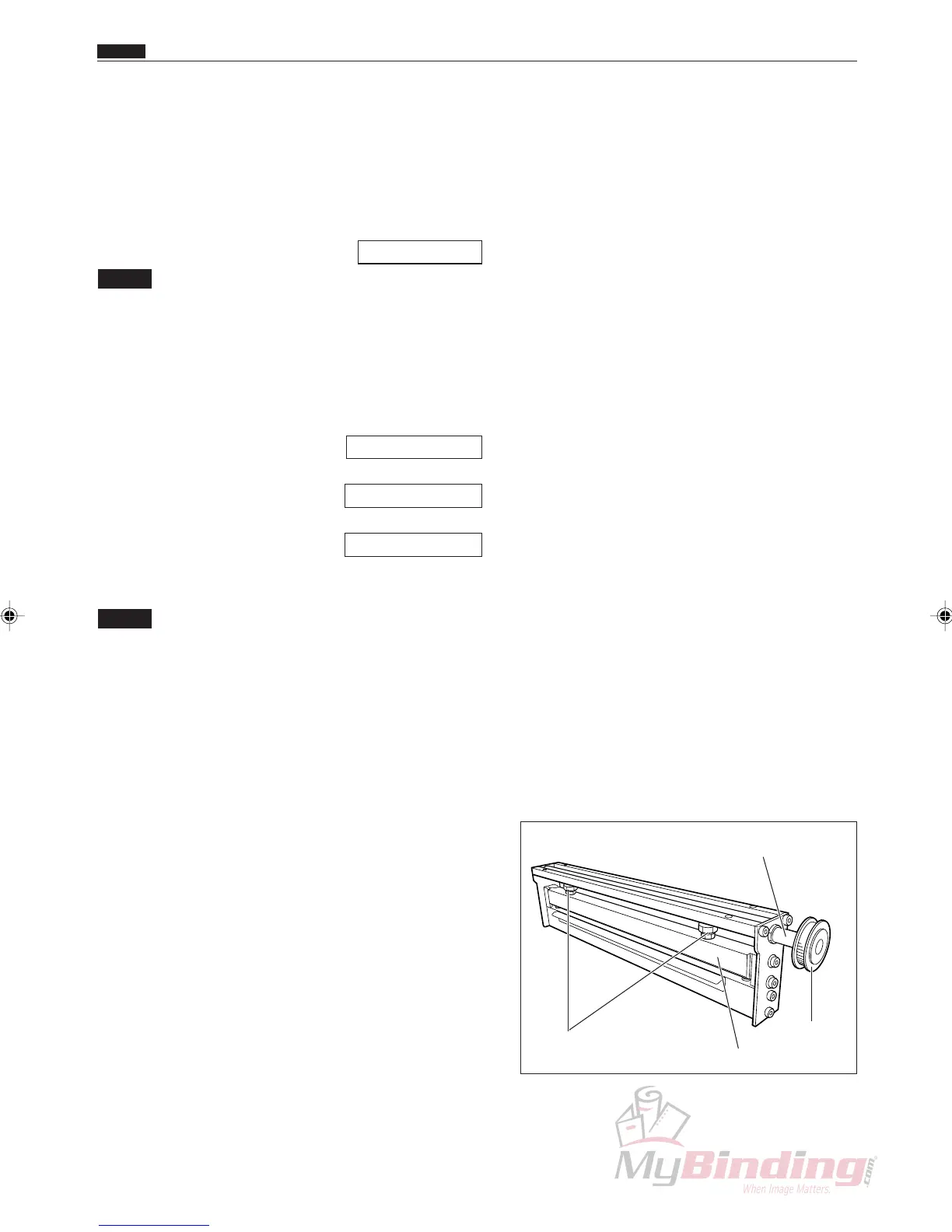
q Place the Creaser Assembly in the “upright” position
(normal operating orientation) on a stable surface.
w Loosen the two lock nuts, as shown in Figure.
e Rotate the Creaser Assembly pulley unit the eccen-
tric shaft has reached it lowest point.
r Place a 0.6 mm feeler gauge between the Creaser
Blades, making certain the gauge does not interfere
with the raised area on the male creaser blade.
Rotate each adjusting bolt clockwise to increase the
gap size (or counterclockwise to decrease the gap
size).
t Tighten each lock nut while holding the respective
adjusting bolt.
y Verify the gap size and readjust if necessary.
n Adjusting Crease Depth
Chap.4
Eccentric Shaft
Pulley Unit
Upper Blade
Lock Nuts