76
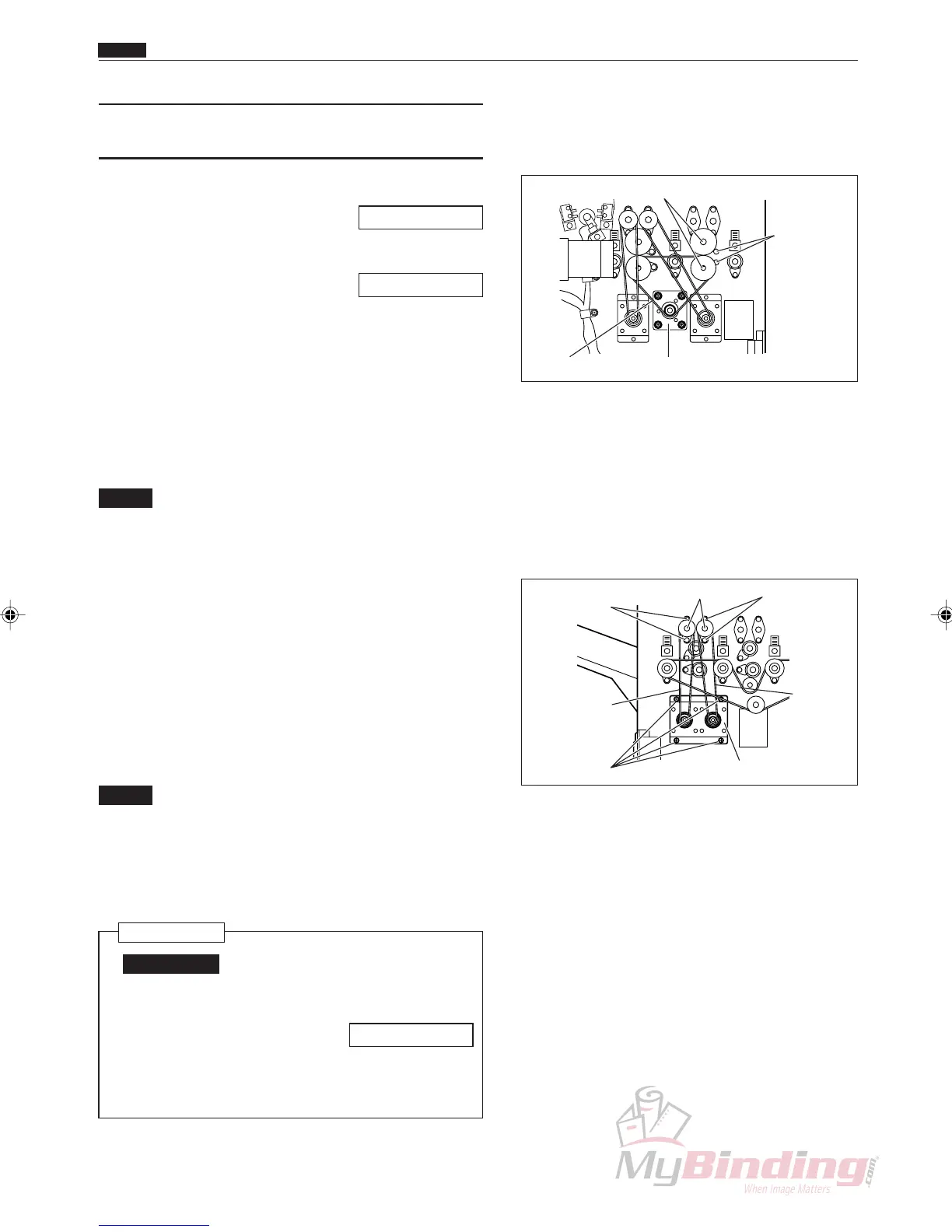
(11) Removing the Optional Slitter 1 and
the Optional Slitter 2
q Remove the cover R unit from the DC-545.
\See page 49
w Remove the cover L unit from the DC-545.
\See page 50
e Loosen the 4 screws on the motor plate, and remove
the timing belt. (1 position)
r Take out the screw, and remove the clamper.
(2 positions)
t Face the key groove on the shaft downwards, and
pull it out on the operation side. (2 positions)
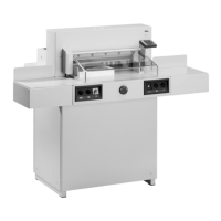
NOTE :
• Do not drop the bearings from opposite the
operation side into the machinery.
(2 positions)
• Do not drop the optional slitter 1 or the
optional slitter 2 into the machinery.
(4 positions)
y Loosen the 4 screws on the motor plate on optional
slitter 1 and optional slitter 2, and remove the
position belt. (2 positions)
u Take out the 3 screws, and remove the lead screw.
(2 Positions)
NOTE :
• Do not drop the collar or disc that are on the
lead screw into the machinery.
• Do not install the optional slitter 1 and the
optional slitter 2 in the wrong positions
during assembly.
Reinstallation
IMPORTANT:
• Make adjustments after installing the
slitter.
\See page 95
• Adjust the play in the Lead Screw to be
less than 0.1 mm.
Motor Plate
Shafts
Clampers
& Screws
Timing Belt
Lead Screws Screws
Screws
Screws
Position
Belt
Position Belt
Motor Plate
Chap.3
m Center Slitter Section