108
⁄0 Creaser Perpendicularity Adjustment
⁄0 Creaser Perpendicularity Adjustment
Chap.4
1. Objective
Adjusting the perpendicularity of the creaser assembly.
• Removing the Creaser Assembly
\See page 70
NOTE :
• You need to adjust the sensor plate after
installing the creaser assembly.
\See page 118
• You need to adjust the creaser perpendicu-
larity and creaser calibration after adjusting
the sensor plate.
\See page 100
2. How to make adjustments
q Prepare some paper that is either 8
1
/2” x 11”, A4
size, or use the adjustment sheet.
w Turn on the power.
e Select P-79. Turn off both bar code and reg. mark.
NOTE :
• Use a JOB that has the Cut 1 set to 10.0 mm
and SCR 1 set to 114.0 mm when the preset
program P-79 have been overwritten.
\See page 155
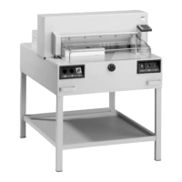
r Adjust the creaser assembly screws so it is parallel
with the leading edge of the paper. (4 positions)
Screws