70
n Creaser Section
Chap.3
(3) Removing the Creaser Assembly
q Remove the cover R unit from the DC-545.
\See page 49
w Remove the cover L unit from the DC-545.
\See page 50
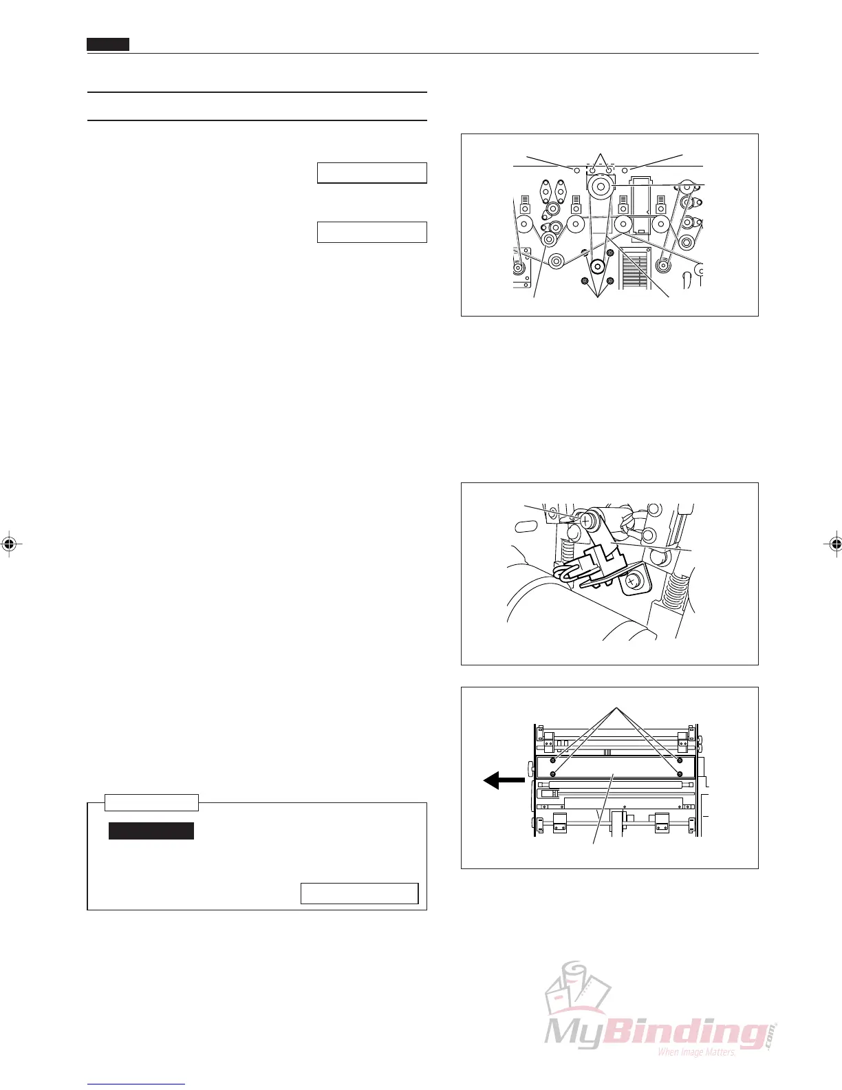
e Take out the screw, and remove the cover (front).
r Take out the screw, and remove the cover (rear).
t Take out the 4 screws, and remove the upper cover.
y Take out the 4 screws, and remove the creaser belt.
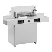
u Take out the screw, and remove the pillar from the
main rear drive.
i Remove the timing belt.
o Take out the screws, and remove the sensor plate.
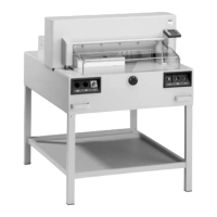
!0 Take out the 4 screws from the auxiliary plate
(upper).
!1 Pull the creaser assembly out opposite the operation
side.
Reinstallation
IMPORTANT:
• Make adjustments after installing the
creaser assembly.
\See page 108
Timing Belt
Cover (Rear)
& Screw
Upper Cover & Screws
Cover (Front)
& Screw
Creaser
Assembly
Pillar & Screw Screws
Auxiliary Plate (Upper)
Screws
Sensor
Plate
Screw