88
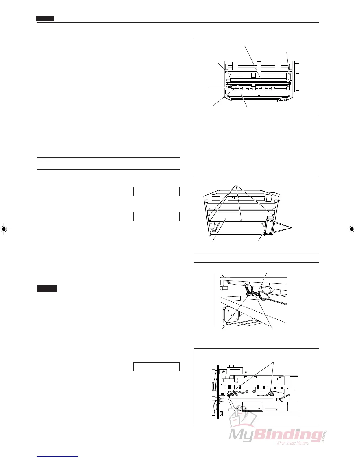
!4 Remove the spring from the 2nd roller (upper).
(2 positions)
!5 Remove the E rings from the 2nd roller (upper),
and remove the bushes. (2 positions each)
!6 Remove the 2nd roller (upper).
!7 Take out the 6 screws, and remove the plate.
!8 Take out the 2 screws, and remove the photodiode
PPS1 and PPS2.
Ref. Photodiode: Brown, blue
Phototransistor: White, blue
(6) Removing the PPS3 Phototransistor
q Remove the cover R unit from the DC-545.
\See page 49
w Remove the cover L unit from the DC-545.
\See page 50
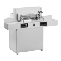
e Take out the 4 screws, and remove the auxiliary
plate.
r Take out the 4 screws, and remove the lid.
t Remove the connector from the inside of the frame.
(1 position)
NOTE :
• There are three connectors in a row. They are
in order from the feeder, the PPS1 photo-
diode, the PPS2 photodiode, and the PPS3
phototransistor. Do not install them in the
wrong position.
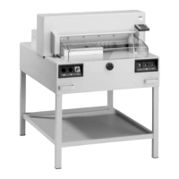
y Remove the cable cramp. (2 positions)
u Remove the margin slitter L.
\See page 64
i Open the cover of the DC-545.
o Take out the 2 screws, and remove the plate.
!0 Remove the springs from the 4th roller (upper).
(2 positions)
Screws
Screws
Lid Auxiliary Plate
Chap.3
. Electric Section
Front Plate
Right Margin Slitter
Position motor
Plate
PPS1
Phototransistor
Connector
Guide Plate Unit
2nd Roller
Connector (PPS1) Connector (PPS2)
Connector (PPS3)
Cable Cramp