67
b Cutter Section
Chap.3
b Cutter Section
(1) Removing the Cutter Assembly
q Remove the cover R unit from the DC-545.
\See page 49
w Remove the cover L unit from the DC-545.
\See page 50
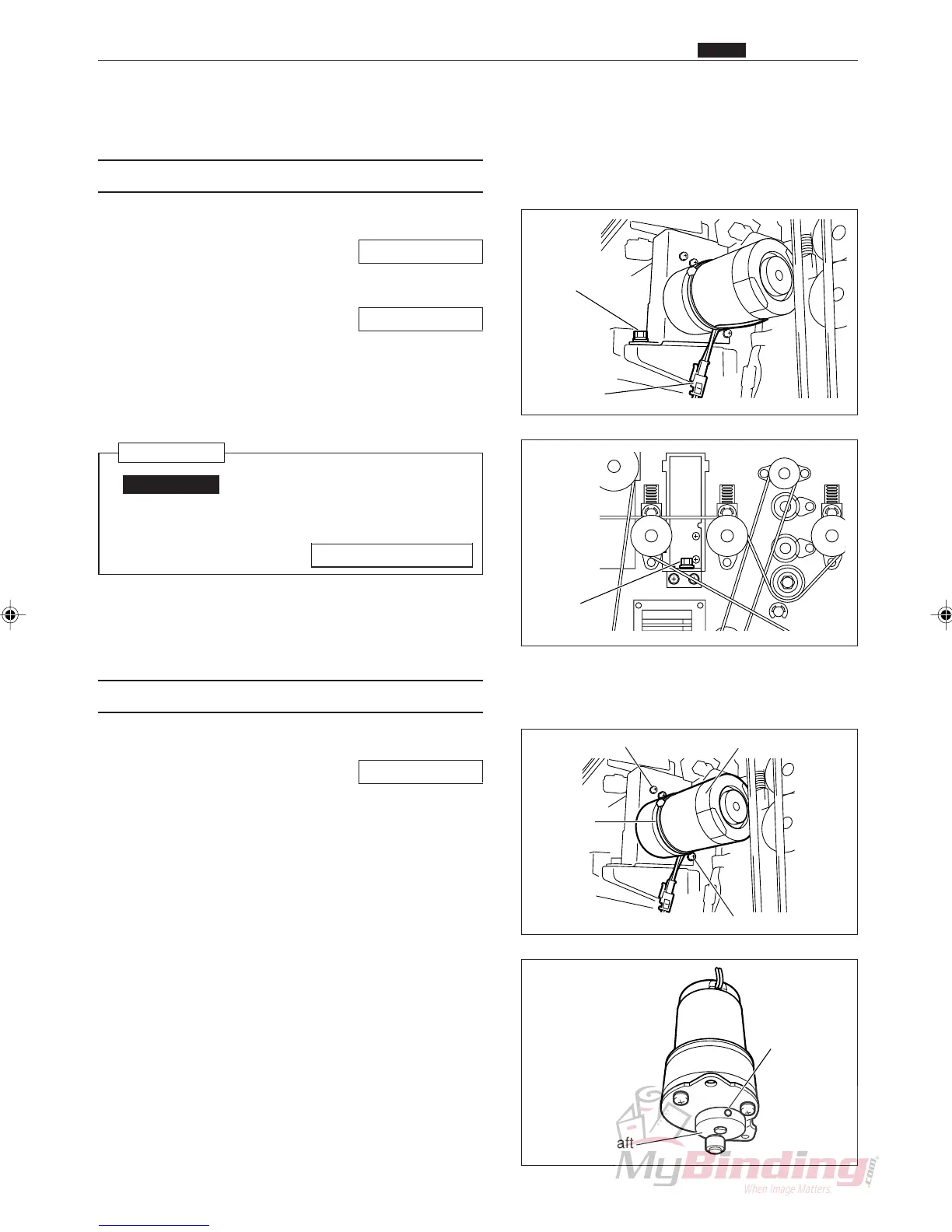
e Remove the connector for the motor. (1 position)
r Take out the 2 screws, and remove the cutter
assembly.
Reinstallation
IMPORTANT:
• Make adjustments after installing the
cutter assembly.
\See page 98, 107
(2) Removing the Cutter Motor
q Remove the cutter assembly.
\See page 67
w Take out the 2 screws, and remove the cutter motor
assembly.
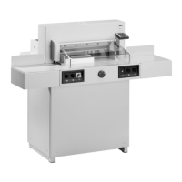
e Loosen the set screws, and remove the eccentric
shaft.
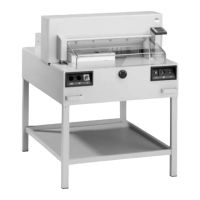
r Take out the 3 screws, and remove the cutter motor.
Screw
Screw Cutter Motor Assembly
Tie Wrap
Set Screw
Eccentric Shaft
Connector
Screw
Screw