107
. Cutter Assembly Perpendicularity Adjustment
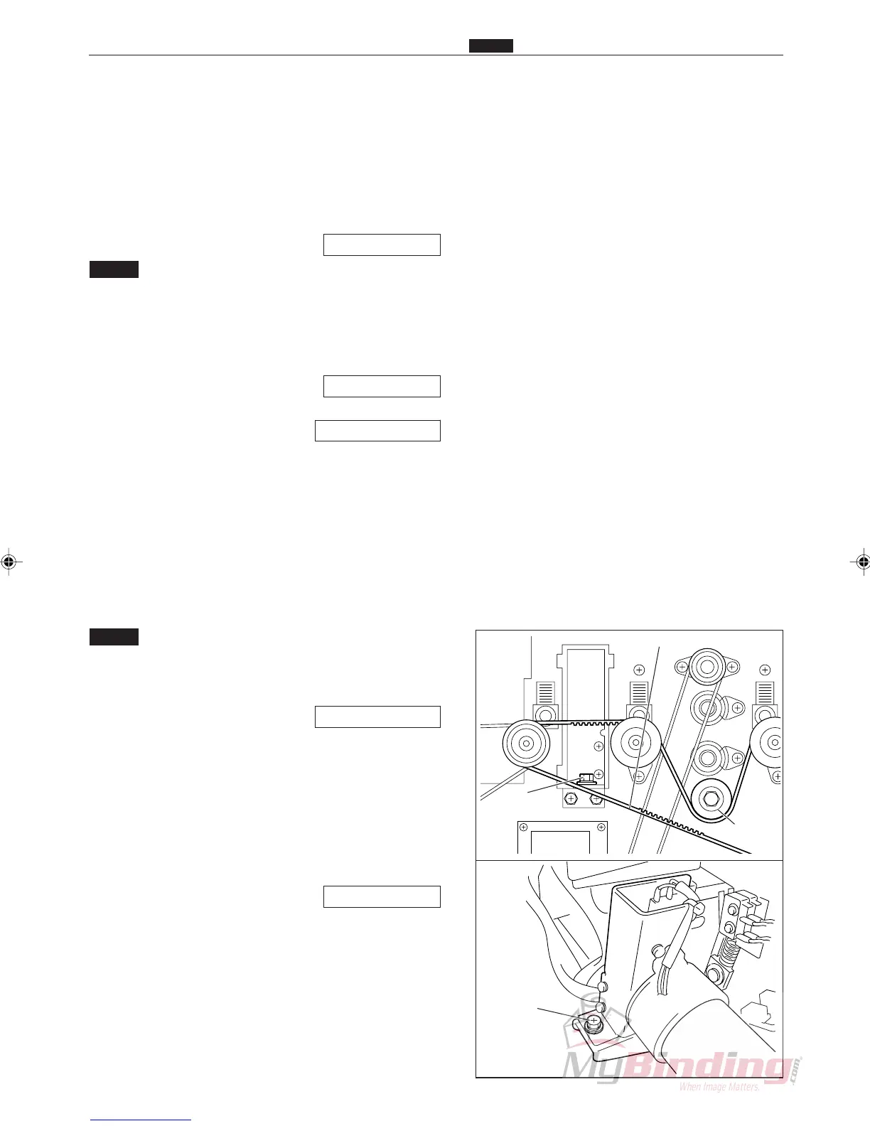
Pillar
Main Belt (Front)
Screw
Screw
. Cutter Assembly Perpendicularity Adjustment
Chap.4
1. Objective
Adjusting the perpendicularity of the cutter assembly.
• Removing the Cutter Assembly
\See page 67
NOTE :
• Do this procedure first before you install the
cutter assembly, and then adjust the cutter
registration and the creaser calibration.
• Cutter Registration Adjustment
\See page 98
• Creaser Calibration Adjustment
\See page 100
2. How to make adjustments
q Prepare some paper that is either 8
1
/2” x 11”, A4
size, or use the adjustment sheet.
w Turn on the power.
e Select P-79. Turn off both bar code and reg. mark.
NOTE :
• Use a JOB that has the Cut 1 set to 10.0 mm
when the preset program P-79 have been
overwritten.
\See page 155
• Put a mark on the leading edge of the paper
that falls into the waste tray for confirmation
when you can measure it.
r Adjust the cutter assembly screws so that the cut off
leading edges are parallel. (2 positions)
t Adjust the cutter registration after installation.
\See page 98