87
(5) Removing the PPS1 and PPS2 Photo-
diode
q Remove the cover R unit from the DC-545.
\See page 49
w Remove the cover L unit from the DC-545.
\See page 50
e Remove the right margin slitter position motor.
\See page 60
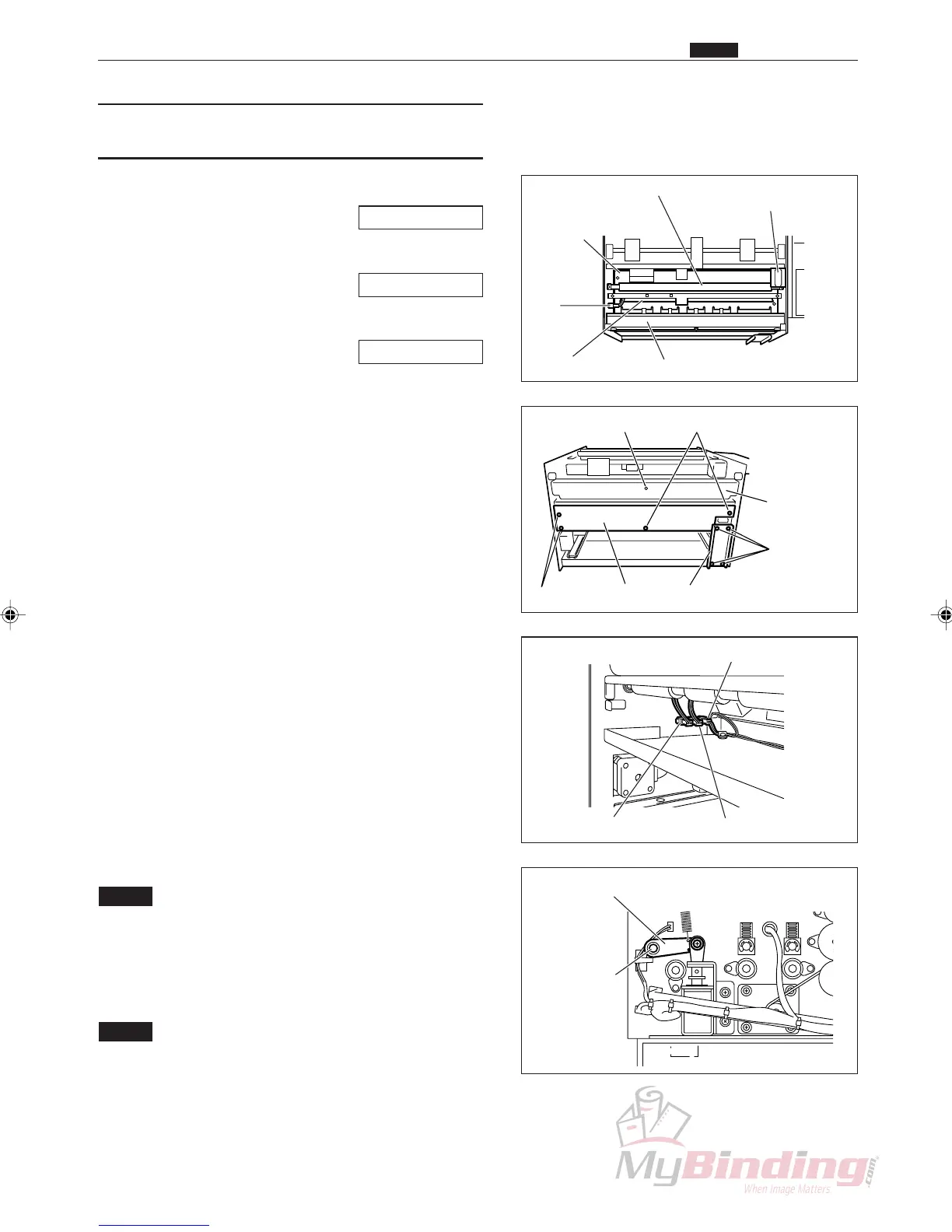
r Take out the 4 screws, and remove the auxiliary
plate.
t Take out the 4 screws, and remove the lid.
(1 position)
y Remove the connector for the feed lamp.
u Take out the 4 screws, and remove the front plate.
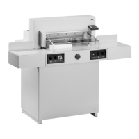
i Loosen the set screws on the lever unit on the
operation side.
o Remove the E ring opposite the operation side, and
remove the bush.
!0 Remove the square shaft.
!1 Remove the connector for the PPS1 phototransistor.
(1 position)
!2 Take out the 2 screws, and remove the guide plate
unit.
NOTE :
• You need to make adjustments during
installation.
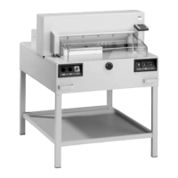
!3 Remove the connector from the inside of the frame.
(1 position)
NOTE :
• There are three connectors in a row. They are
in order from the feeder, the PPS1 photo-
diode, the PPS2 photodiode, and the PPS3
Phototransistor.Do not install them in the
wrong position.
Lever Unit & Set Screw
Square Shaft
Front Plate
Right Margin Slitter
Position motor
Plate
PPS1
Phototransistor
Connector
Guide Plate Unit
2nd Roller
Screws
Front Plate
Screws
Screws Lid Auxiliary Plate
Feed Lamp
. Electric Section
Chap.3
Connector (PPS2)Connector (PPS1)
Connector (PPS3)