19
3. Operation of each unit
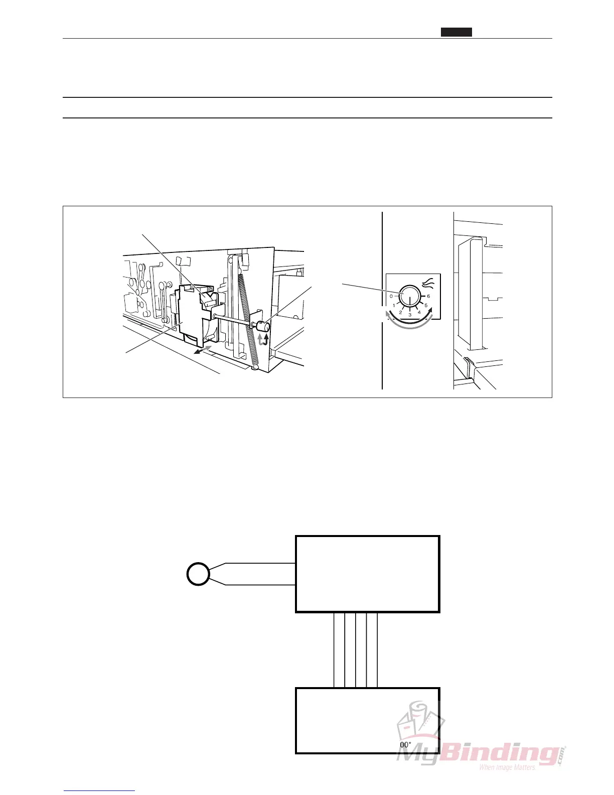
(1) Fan (blower)
Description
Paper on the feed tray is transferred to the blower and several sheets are floated up.
The airflow of the blower is adjusted by changing the position of the shutter and fan unit.
The level the paper is floated up is adjusted by changing the airflow of the blower and the paper level sensor.
The fan (blower) is usually running during processing.
Operation
The blower airflow can be increased by turning the knob so the numbers increase.
The gap between the shutter and the fan increases, which increases the air intake and therefore increases the
amount of air blown out.
The blower airflow can be decreased by turning the knob so the numbers decrease.
The gap between the shutter and the fan decreases, which decreases the air intake and therefore decreases the
amount of air blown out.
Circuit diagram
Shutter
Fan (Blower)
Knob
Chap.2
z Paper Feed Unit
RED
BLACK
CN2-3
24V
FAN(Exhaust)
GND
GND
24V
CN1-1CN1-1
-3
-12
CN11-10
-19
-3
-12
-17
-18
-4
FAN(Blower)
N4-X105*
Feed P.W.B. unit
N4-V303*
Main P.W.B. unit
N4-V300*
M