125
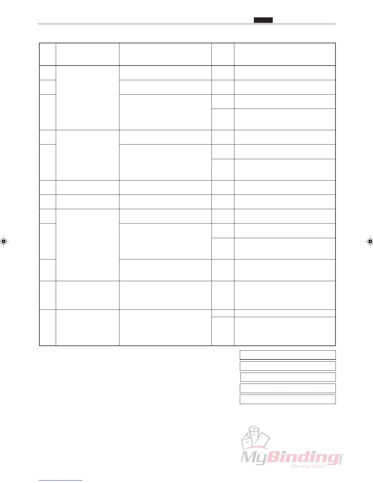
z Troubleshooting Guide
Chap.6
Pro-
ce-
dure
Does it operate in HELP mode
(H-30)?
Is the connector for the fan
(suction) firmly plugged in?
Is the voltage measured with a
tester between CN2-3 (+) and
CN2-4 (GND) on the feed PCB
unit +24 V (DC) while the fan
(blower) is operating?
Is it normal when checked in
HELP mode (H-08)?
Is the voltage measured with a
tester between CN4-12 (+) and
CN4-13 (GND) on the feed
PCB unit +5 V (DC), is it 0 V
(DC) during light transmission?
Are the AF-100 and the DC-
545 firmly connected?
Is it normal when checked in
HELP mode (H-10)?
Does it operate when in HELP
mode (H-11)?
Is the voltage measured with a
tester between CN6-1 (+) and
CN6-2 (GND) on the main
PWB unit +24 V (DC) while the
feed solenoid is operating?
Is the press pressure too weak
when the feed solenoid is
operating?
Does it operate normally if you
open a gap between the Front
Plate (N4-A1190) and Plate
(N4-A1210)?
Is the trouble cleared by
replacing the feed PCB unit?
Fan (suction)
Paper level sensor
Connections
Feed motor
Feed solenoid
Front Plate
Feed PCB unit
11
12
13
14
15
16
17
18
19
20
21
22
Cause/Defective part
Result
Countermeasure
Yes
No
Yes
No
Yes
No
No
No
No
Yes
Yes
No
Yes
Yes
Yes
No
Go to procedure 14.
Plug the connector in firmly.
Replace the fan (blower).
Go to procedure 18.
Go to procedure 16.
Replace the sensor.
Go to procedure 21.
Connect them firmly.
Replace the feed motor.
Go to procedure 20.
Replace the feed solenoid.
Replace the main PWB unit.
Adjust the press pressure.
Finish
Finish
Check the wire bundles and the
connectors, and if there are not
problems, replace the main PWB
unit.
Items to be checked
HELP mode H-08 \ see p.143
HELP mode H-10 \ see p.143
HELP mode H-11 \ see p.144
HELP mode H-30 \ see p.149
HELP mode H-31 \ see p.149