38
Chap.2
n Center Slitter
Possible range for each slitter
Name Possible range Comments
Left center slitter 0 to 160 mm Example:
Right center slitter Left center slitter position +50 mm to 320 mm When the left center slitter is set
at 120.2 mm, settings from
170.2 are possible.
OP1 slitter 0 to 320 mm (when OP2 is not installed.)
0 to 160 mm (OP2 is installed)
OP2 slitter OP1 position +50 mm to 320 mm Example:
(This is an optional slitter) When the OP1 is set at 110.0
mm, settings from 160.0 mm are
possible.
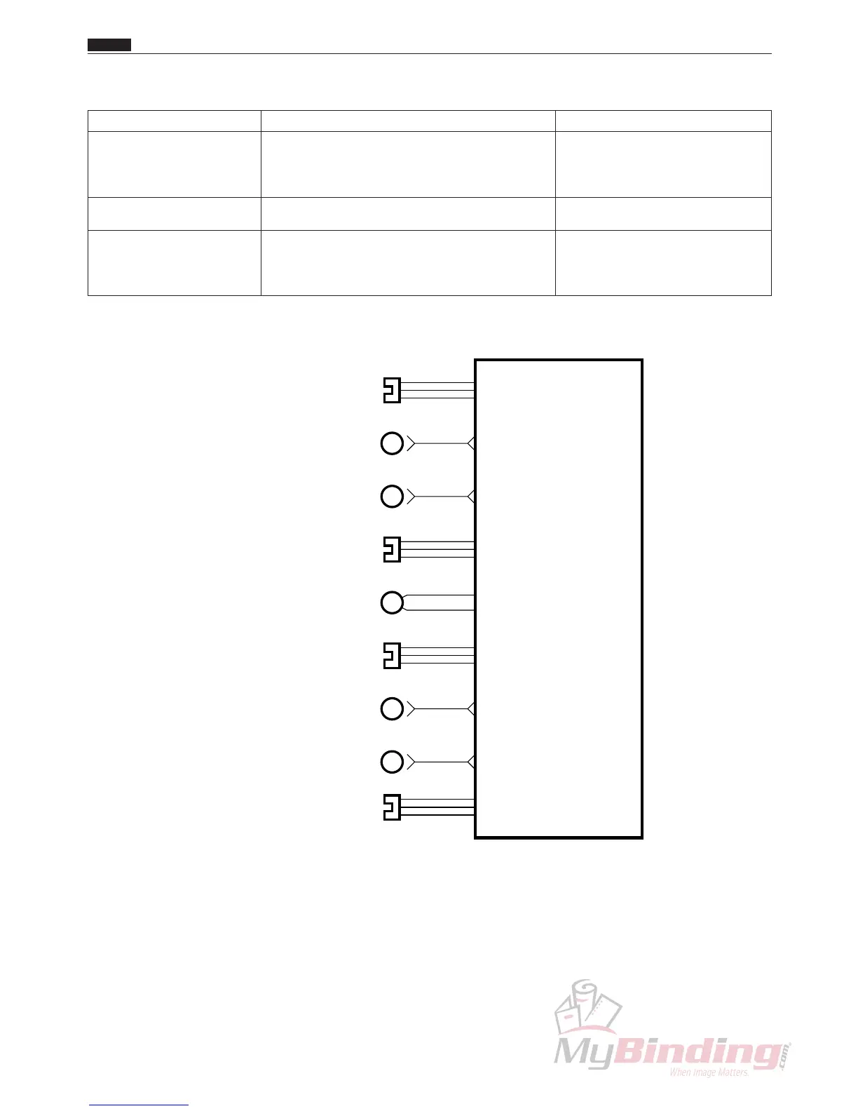
Circuit diagram
CN6-9
-9
-8
CN8-7
3
2
1
BLUE
PEACH
RED
-18
CN7-13
-10
Main P.W.B. unit
N4-V300*
-26
-25
CN4-24
3
2
1
BLUE
ORANGE
RED
M
M
-12
CN7-7
M
~~
Left Center Slitter Sensor
CA003
Right Center Slitter Sensor
CA003
Slitter Driving Motor
L8-X1010
Left Center Slitter Position Motor
M7-X111*
Right Center Slitter Position Motor
M7-X111*
-6
CN14-1
-9
-8
CN9-7
3
2
1
BLUE
PURPLE
RED
M
-6
CN9-1
M
~~
OP1 Slitter Sensor
CA003
-9
-8
CN14-7
3
2
1
BLUE
PURPLE
RED
OP2 Slitter Sensor
CA003
OP1 Slitter Position Motor
M7-X111*
OP2 Slitter Position Motor
M7-X111*