4-6
Chapter 4 I/O SETTINGS
ZW
User’s Manual
Chapter 4
I/O Terminal Names and Functions
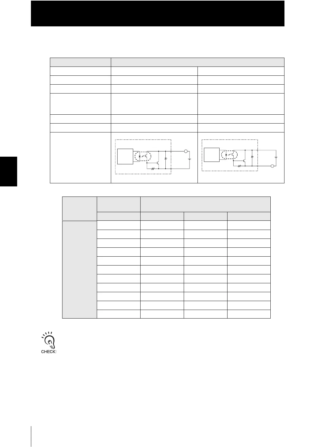
■ Output circuit
*1 Below is a table giving the COM_OUT (output common) and output signal connection correspondence.
Connect a load that matches the output specifications. Short-circuit can cause sensor breakdown.
Item Specifications
Model ZW-C10T/C10AT ZW-C15T/C15AT
Output type NPN PNP
Output voltage DC21.6 to 30 V DC21.6 to 30 V
Load current 20-pole terminal block: 50 mA max.
52-pole extension connector:
30 mA max.
20-pole terminal block: 50 mA max.
52-pole extension connector:
30 mA max.
ON residual voltage 1.2 V max. 1.2 V max.
ON leakage current 0.1 mA max. 0.1 mA max.
Internal circuit diagram
*1
Terminal
name
20-pole terminal
block
52-pole extension connector
COM_OUT1 COM_OUT2 COM_OUT3 COM_OUT4
Output
terminal name
HIGH1 BINARY_OUT1 GATE BINARY10
PASS1 BINARY_OUT2 BINARY0 BINARY11
LOW1 BANK_OUT1 BINARY1 BINARY12
ALARM1 BANK_OUT2 BINARY2 BINARY13
BUSY1 BANK_OUT3 BINARY3 BINARY14
ENABLE BINARY4 BINARY15
BINARY5 BINARY16
BINARY6 BINARY17
BINARY7 BINARY18
BINARY8 BINARY19
BINARY9 BINARY20
L
COM_OUT1/2/3/4
㪂
Internal
circuit
Output
terminals
Load
㪣
㪂
COM_OUT1/2/3/4
Internal
circuit
Output
terminals
Load

 Loading...


