Chapter 4 I/O SETTINGS
Chapter 4
I/O Signal Functions
4-7
ZW
User’s Manual
I/O Signal Functions
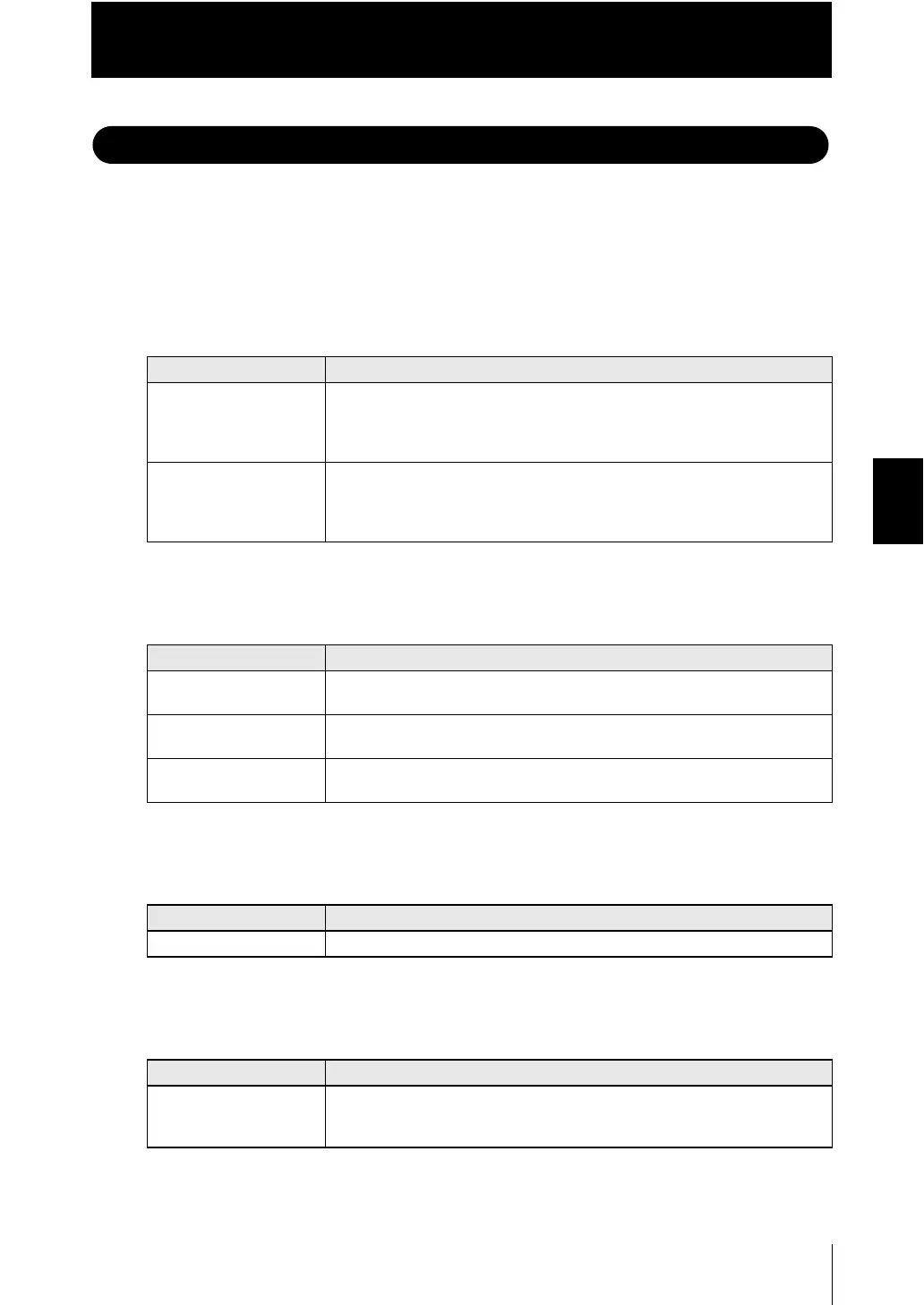
The following describes the functions of I/O signals.
■ 20-pole terminal block
●
Analog output
●
Judgment output
●
ALARM output
●
BUSY output
Name Description
Analog voltage output This outputs the measured value, from -10 V to +10 V as the voltage value.
When measurement not possible: Approx. +10.8 V (default value; can be
selected by user)
Alarm: Approx. +10.8 V
Analog current output This outputs the measured value; from 4 mA to 20 mA as the current value.
When measurement not possible: Approx. +21 mA (default value; can be
selected by user)
Alarm: Approx. +21 mA
Name Description
HIGH output This outputs judgment results - HIGH (HIGH threshold values Measured
value).
PASS output This outputs judgment results - PASS (LOW threshold values Measured
value HIGH threshold values).
LOW output This outputs judgment results -LOW (LOW threshold values Measured
value).
Name Description
ALARM output This turns ON when there is a system error.
Name Description
BUSY output This turns ON during sampling with the hold function enabled.
It allows you to check whether or not the self-trigger is functioning correctly. It
also turns ON during bank switching.

 Loading...


