6-8
Chapter 6 SPECIFICATIONS AND EXTERNAL DIMENSIONS
ZW
User’s Manual
Chapter 6
Controller
Controller
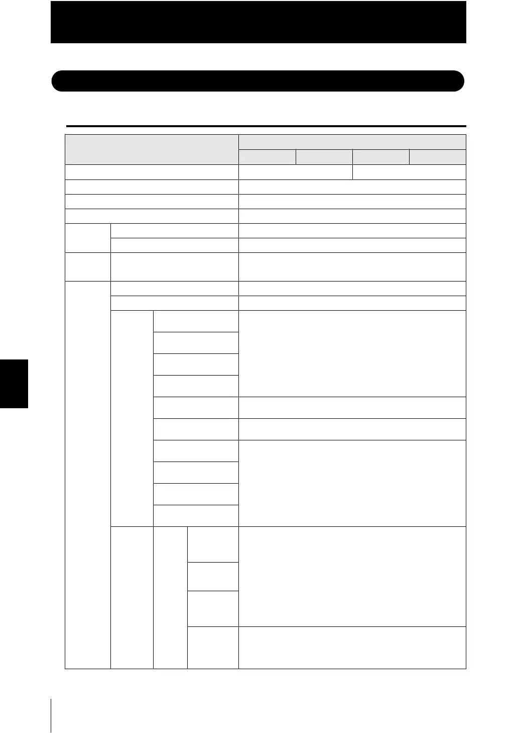
Specifications
Item
Specifications
ZW-C10T ZW-C10AT ZW-C15T ZW-C15AT
Input/Output type NPN PNP
Number of connected Sensor Heads 1 per Controller
Sensor Head compatibility Available
Light source for measurement White LED
Segment
display
Main display 11-segment red display, 6 digits
Sub-display 11-segment green display, 6 digits
LED
display
Status indicators HIGH (orange), PASS (green), LOW (orange), STABILITY
(green), ZERO (green), ENABLE (green), THRESHOLD-H
(orange), THRESHOLD-L (orange), RUN (green)
External
interface
Ethernet 1 port , 100BASE-TX, 10BASE-T
RS-232C 1 port, 115,200 bps max.
20-pole
terminal
block
Judgment output
(HIGH1/PASS1/LOW1)
Transistor output system
Output voltage: 21.6 to 30 VDC
Load current: 50 mA or less
Residual voltage when turning ON: 1.2 V or less
Leakage voltage when turning OFF: 0.1 mA or less
BUSY output
(BUSY1)
ALARM output
(ALARM1)
ENABLE output
(ENABLE)
Analog voltage output
(OUT1V)
-10 to +10 V, Output impedance: 100
Analog current output
(OUT1A)
4 to 20 mA, Max. load resistance: 300
LED OFF input
(LED OFF1)
DC input system
Input voltage: 24 VDC ±10 % (21.6 to 26.4 VDC)
Input current: 7 mA Typ. (24 VDC)
Voltage/Current when turning ON: 19 V/3 mA or more
Voltage/Current when turning OFF: 5 V/1 mA or less
ZERO RESET input
(BUSY1)
TIMING output
(TIMING1)
RESET output
(RESET1)
52-pole
extension
connector
Binary Measured
value output
(BAINARY
0 to 20)
Transistor output system
Output voltage: 21.6 to 30 VDC
Load current: 50 mA or less
Residual voltage when turning ON: 1.2 V or less
Leakage voltage when turning OFF: 0.1 mA or less
Gate signal
output
(GATE)
Selected
task output
(BINARY_
OUT1/2)
Selected
task input
(BAINARY_
SEL1/2)
DC input system
Input voltage: 24 VDC ±10 % (21.6 to 26.4 VDC)
Input current: 7 mA Typ. (24 VDC)
Voltage/Current when turning ON: 19 V/3 mA or more
Voltage/Current when turning OFF: 5 V/1 mA or less

 Loading...


