Chapter 1 MEASUREMENT SETUP
Chapter 1
About Installation and Connection
1-7
ZW
User’s Manual
About Installation and Connection
■ Checking the installation environment
Read “Precautions for safe use” at the beginning of this manual, and check the
installation environment.
Precautions for safe use p.6
■ Checking the installation site
Read “Precautions for correct use” at the beginning of this manual, and check the
installation site.
Precautions for correct use p.8
Installation of Sensor Head
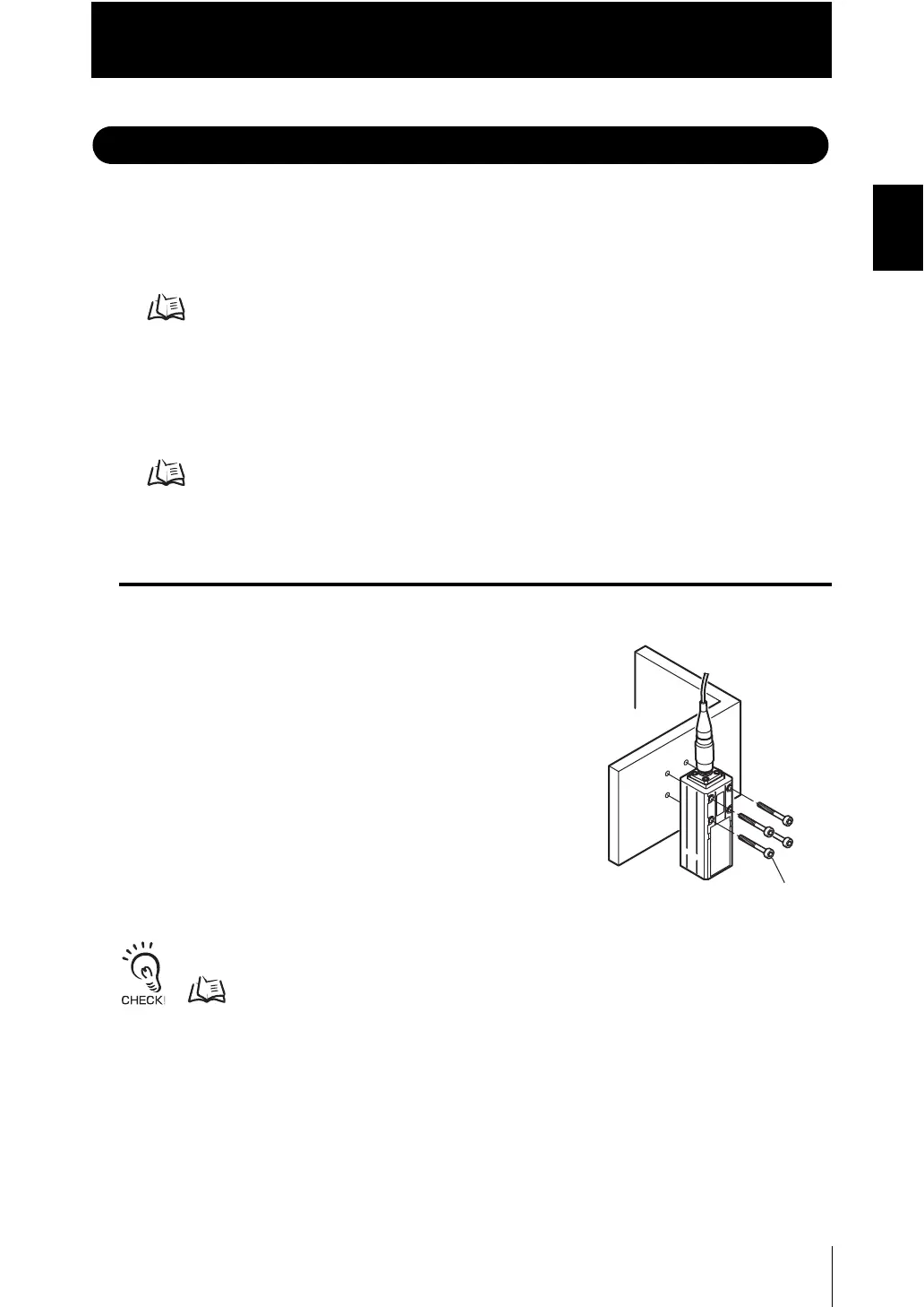
■ Installation procedure
Place the Sensor Head with an appropriate distance
from the target to measure, fixing it by tightening four
M3 screw inserted into their respective installation
holes.
Tightening torque: 0.54 Nm
• For the location screw holes, see the external dimensions.
External Dimensions p.6-3
• When measuring on a high-reflectivity workpiece, such as a mirror or wafer, false measured values
beyond the measuring range may be outputted. When a workpiece with diffuse reflection is used, we
recommend installing and adjusting while watching the position of the spot.
M3 screw×4

 Loading...


