1-8
Chapter 1 MEASUREMENT SETUP
ZW
User’s Manual
Chapter 1
About Installation and Connection
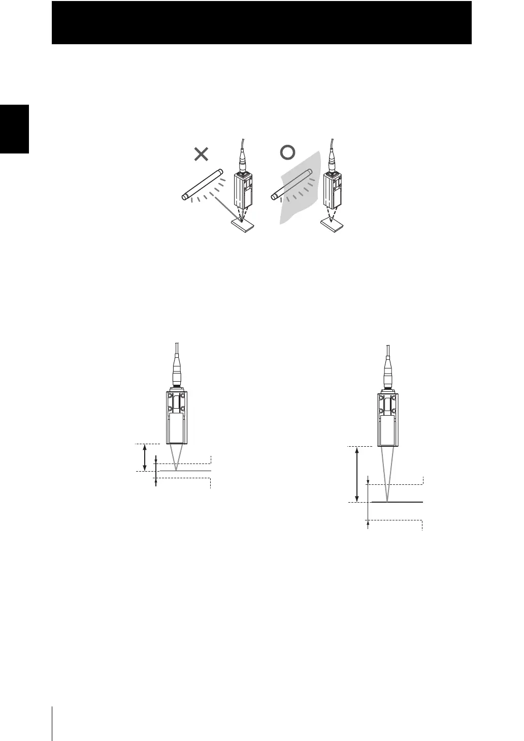
● Basic precautions for installation
Do not install the Sensor Head in a place where strong light hits the laser emitter/
receiver section of the Sensor Head. Also, if a workpiece has a shiny surface, the light
from the lighting will be reflected and a malfunction may occur. In such a case, prevent
reflection by, for example, covering the light to stop reflection.
■ Measuring range
With the ZW series, the measurement center distance is expressed as 0 with the NEAR
side as + and the FAR side as -.
Measurement center
distance㪑㩷20 mm
NEAR side㪑㩷㪂1 mm
Measuring
center㪑㩷0 mm
FAR side㪑㩷㪄1 mm
Measuring range
●ZW-S20
●ZW-S40
Measurement center
distance㪑㩷40 mm
NEAR side㪑㩷㪂6 mm
Measuring
center㪑㩷0 mm
FAR side㪑㩷㪄6 mm
Measuring range

 Loading...


