4-2
Chapter 4 I/O SETTINGS
ZW
User’s Manual
Chapter 4
I/O Terminal Names and Functions
I/O Terminal Names and Functions
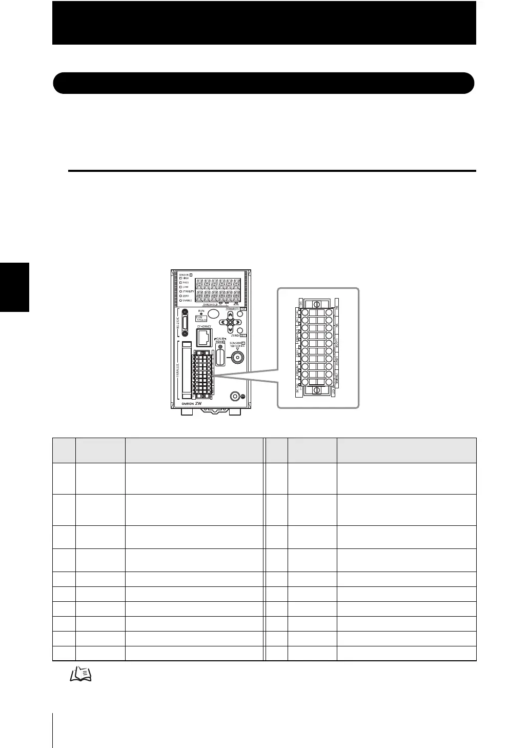
The following describes the names and functions of the Controller I/O terminals (20-pole
terminal block, 52-pole extension connector).
I/O Terminal Functions
The following summarizes the I/O terminals and explains their functions.
■ 20-pole terminal block
Used for judgment output, control input, etc.
Compatible cable specifications: AWG 18 to 28, pin processed length: 7 mm
Electrical Specifications p.4-5
Timing Charts p.4-33
No.
Signal
name
Description No.
Signal
name
Description
1 OUT1 (V) Sensor Head 1 analog voltage
output
Outputs the measured value, 10 V
11 NC Not used
2 OUT1 (A) Sensor Head 1 analog current output
Outputs the measured value, to 20
mA
12 NC Not used
3 OUT1 0V 0 V for Sensor Head 1 analog
voltage output
13 NC Not used
4 COM_OUT
1
COM1 for output 14 ALARM1 Sensor Head 1 ALARM output
5 HIGH1 Sensor Head HIGH judgment output 15 BUSY1 Sensor Head 1 BUSY output
6 PASS1 Sensor Head PASS judgment output 16 ENABLE ENABLE output
7 LOW1 Sensor Head LOW judgment output 17 ZERO1 Sensor Head 1 ZERO input
8 COM_IN1 COM1 for input 18 RESET1 Sensor Head 1 RESET input
9 DC24V (-) 0 V input for power supply 19 TIMING1 Sensor Head 1 TIMING input
10 DC24V (+) 24 V input for power supply 20 LED OFF1 Sensor Head 1 LED OFF input
1
2
3
4
5
6
7
8
9
10
11
12
13
14
15
16
17
18
19
20

 Loading...


