10
Introduction
ZW
User’s Manual
Introduction
Editor's Note
Editor's Note
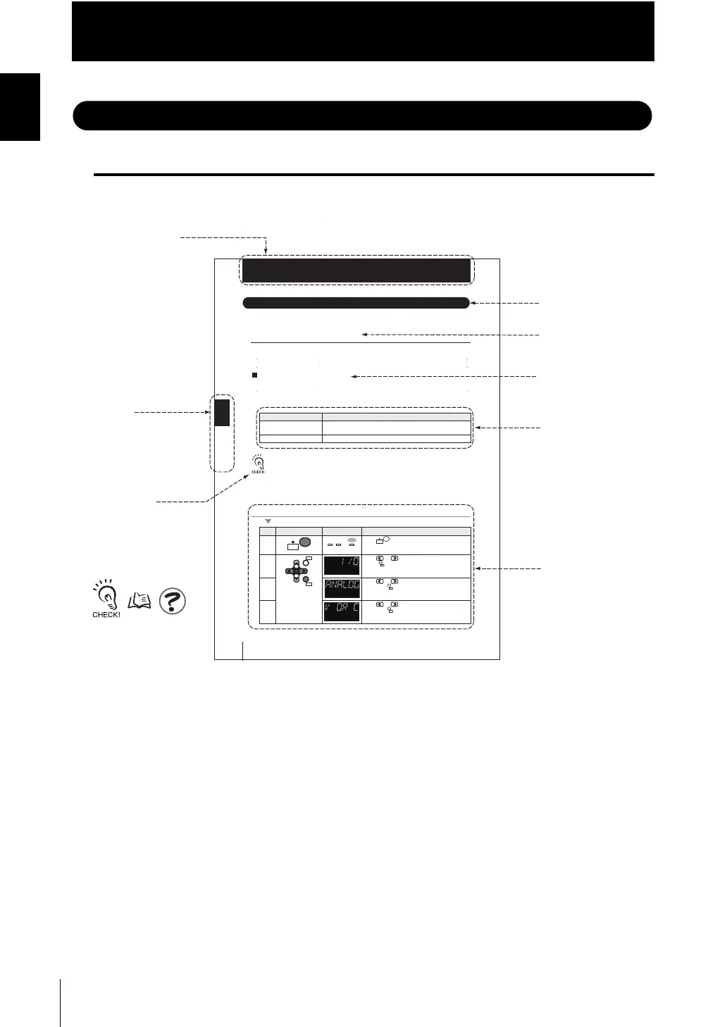
Page Format
■ Meaning of Symbols
Menu items that are displayed on the main or sub-display, and windows, dialog boxes
and other GUI elements displayed on the personal computer are indicated enclosed by
brackets [ ].
╙
┨
╙㪋┨ 䇭㪠㪆㪦⸳ቯ
ജ䈮㑐䈜䉎⸳ቯ
ജ䈮㑐䈜䉎⸳ቯ
4-12
Chapter 4 I/O SETTINGS
ZW
User’s Manual
Chapter 4
Settings for I/O
Settings for I/O
The following describes settings for I/O.
Settings for Analog Output
The following describes the settings for outputting the current measurement results from
the analog output of the 20-pole terminal block.
Output destination setting
With analog output, the measurement results can be output converted into a current
from 4 to 20 mA or a voltage from -10 to +10 V.
Selects which to output, the current or the voltage.
The same output destination is set for all banks. The output destination cannot be set separately for
individual banks.
As an example, here is an explanation of the procedure for outputting the voltage.
Operating procedure
Setting [Display] Description [Display]
Voltage output [VOLT]
(Default value)
Voltage output
Current output [CUR.] Current output
Steps
Key operation Display Description
NUF eht retne ot sdnoces owt rof yek sserP1
mode.
dna "O/I" fo rehtie tceles ot syek ro sserP2
press key.
es ot syek ro sserP3 lect either of "ANALOG"
and press
key.
"C RO V" fo rehtie tceles ot syek ro sserP4
and press key.
RUN
FUN
TEACH
RUN
UNLIT
RUN
FUN
TEACH
ZERORST/
ESC
ZERO/
SET
ZERO/
ZERO/
SET
ZERO/
SET
Title of each chapter
Header
Index label
Supplementary
Explanation
Explanation of
Explanation of options
Explanation of
Operating
procedure
Cross-header
Indicates the chapter
number and title.
Helpful information
regarding operation
and reference pages
are introduced here
using symbols.
Quasi Cross-header
 Loading...


