1-2
Chapter 1 MEASUREMENT SETUP
ZW
User’s Manual
Chapter 1
System Configuration
System Configuration
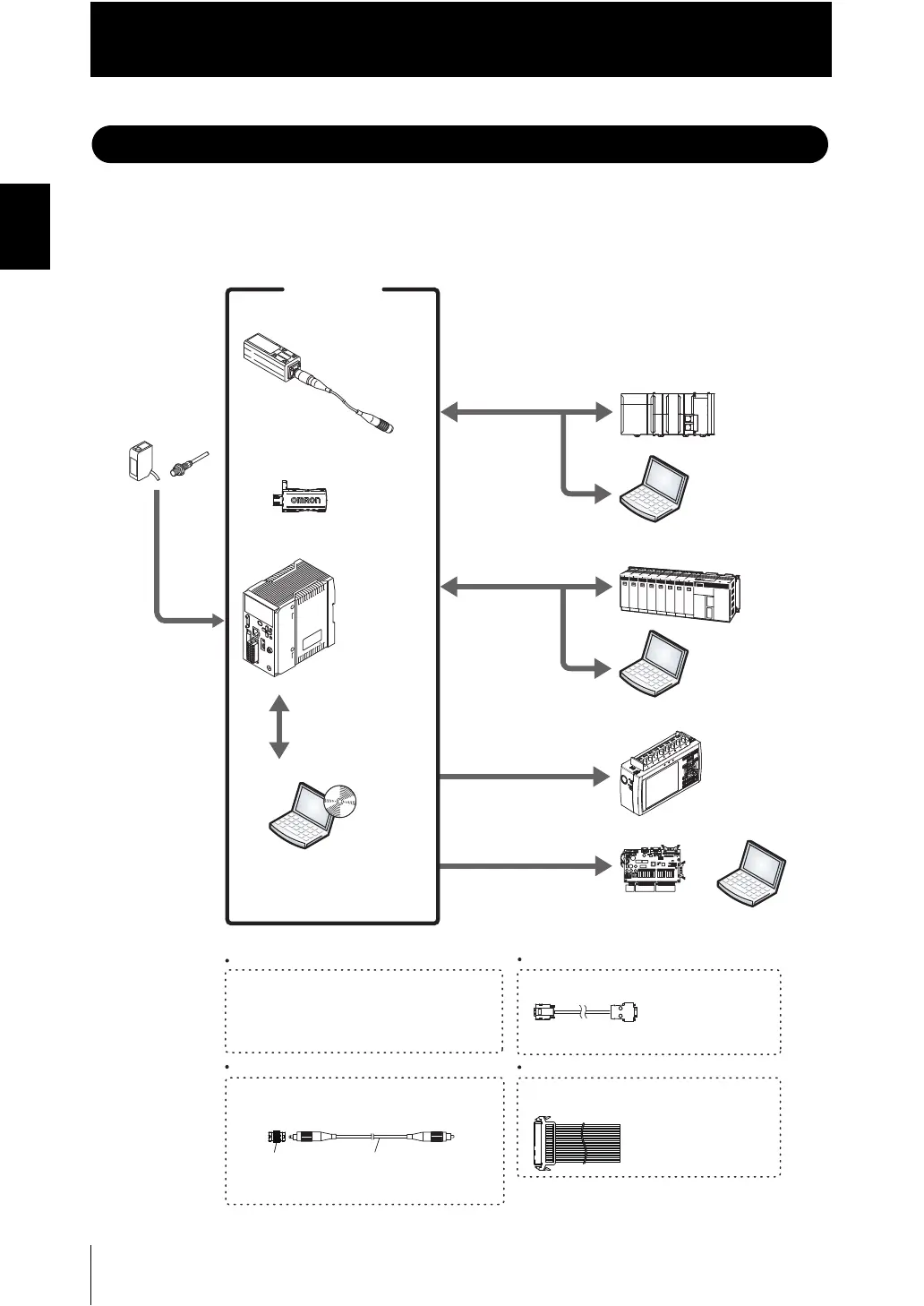
In addition to operations with the basic configuration, ZW series displacement sensors can
support various measurement applications when combined with numerous peripheral
devices.
Photoelectric and
adjacent sensors
ZW series
Basic configuration
RS-232C cable
䇭䇭䇭䇭䇭䇭(note2)
PLC
(Note1)㩷Ethernet cable (sold separately)
For PLC/programmable terminal: ZW-XPT2
For personal computer: ZW-XRS2
Sensor head
Detects a target to
measure.
Controller
PC
PLC
PC
Data loggers, etc.
PC
High-speed
input board
(Note2)㩷RS-232C cable (optional)
Depending on connecting devices, exclusive cables
may be supplied.
Extension fiber cable (optional)
A exclusive extension fiber cable is available to
place the Sensor Head and Controller far apart than
the normal distance to each other.
Use the exclusive product for correct measurements.
Connecting adapter
(included with the fiber
cable for extension)
ZW-XFC
Ethernet (note1)
(Note3)㩷Parallel cable (optional)
A parallel cable for 52-pole extension connector
(ZW-XCP2) with 2 m cable is available.
Smart Monitor ZW
(Exclusive personal
computer software)
ZW-S20
ZW-S40
ZW-C10T/C10AT
ZW-C15T/C15AT
Ethernet (note1)
ZW-SW_ _
Calibration ROM
(included with sensor head)
Associated with
the sensor on a
one-to-one basis
Performs
measurements
and outputs the
result.
Personal
computer
Allows making advanced settings and
checking up measured values easily using
exclusive personal computer software.
Accessory for the Controller
ZW-C10T/C15T.
Measurement data can be easily loaded
into a PLC or personal computer through
Ethernet connections.
The Controller can be remotely controlled
from a personal computer; including switching
between or changing setting data and entering
measuring triggers.
(Communication with multiple devices
simultaneously cannot be achieved via Ethernet.)
Various Controller operations,
including, taking measured values
and judgment results, switching
between or changing setting data
or entering measuring triggers, are
available.
Displaying analog signals in
waveform from measured values
or judgment results in color is
available.
Analog output
Outputting measured values
or judgment results at a high
speed in parallel is available.
Parallel output (note3)
The system receives
trigger signals to
control measuring
timings.
Prepare commercially available Ethernet cable
satisfying the following requirements:
- Category 5e or more, 30 m or less
- RJ45 connector (8-pin modular jack)
- For direct connection: Select cross cable.
- For connection through a network hub: Select straight
cable.
Extension fiber cable
ZW-XF_ _R
(2 m/5 m/10 m/20 m/30 m)

 Loading...


