EasyManuals Logo

Omron ZW Series User Manual

Omron ZW Series
247 pages
To Next Page IconTo Next Page
To Previous Page IconTo Previous Page
Page #209 background imageLoading...
Page #209 background image
Chapter 6 SPECIFICATIONS AND EXTERNAL DIMENSIONS
Chapter 6
Sensor Head
6-3
ZW
User’s Manual
External Dimensions
ZW-S20/S40
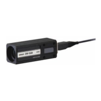
Calibration ROM (ZW-XROM) *
* This comes with the Sensor Head ZW-S20/S40. Be sure to use a Calibration ROM together with the Sensor
Head with the same serial number.
64
16
4
(Unit: mm)
4-φ3.5
Mounting holes
43
16
Measurement
center
M
(Note1)
M
(Note1)
Lighting and
receiving axis
㩿40
Standard fiber cableφ2.0
Connector
16
±0.1
16
±0.1
4
±0.1
43
±
0.1
Standard surface
Mounting hole dimensions
4-M3
24
24
12
Caution
label
Measurement
CENTER
X
(Note1)
L
(Note1)
Measurement
end
FAR
Measurement
end
NEAR
Note 1
Type
L
M
ZW-S20
20 1
ZW-S40
40 6
X
11.8
11.7
φ10
㩿42
㩿50
Standard
surface
Standard
surface
14
3
3.6 6.9
27.4
7
7
15
3.5
3.5
16.5
1.82.6
19
33
φ2.5 mounting hole
Unit: mm

Table of Contents

Other manuals for Omron ZW Series

Questions and Answers:

Question and Answer IconNeed help?

Do you have a question about the Omron ZW Series and is the answer not in the manual?

Omron ZW Series Specifications

General IconGeneral
BrandOmron
ModelZW Series
CategoryAccessories
LanguageEnglish

Related product manuals