Chapter 4 I/O SETTINGS
Chapter 4
Timing Charts
4-47
ZW
User’s Manual
●
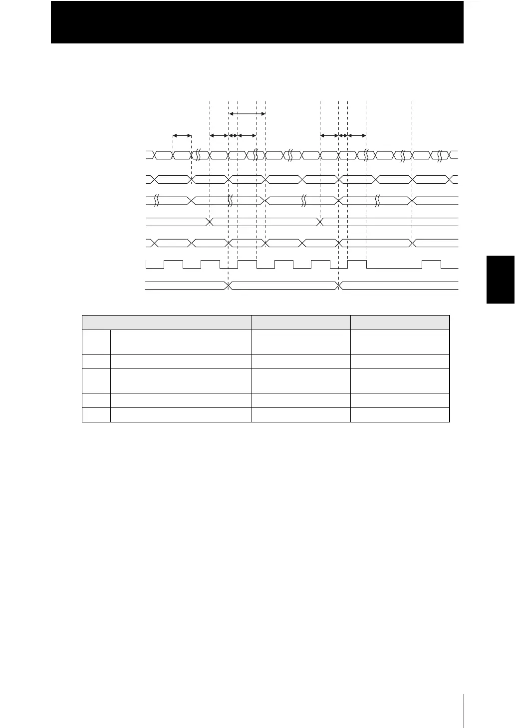
Measured value 2 mode (When measured values for multiple tasks are output by
BINARY_SEL input)
• Explanation of operations (When the results for all tasks are output)
(1) Input the number of the task you want to output to the BINARY_SEL input.
(2) The results for the selected tasks are output (judgment output and binary
output).
(3) After the judgment result and binary data output, the GATE signal is turned ON.
(4) The GATE output time after the GATE signal is turned ON, the GATE signal is
turned OFF.
(5) When the results for the selected tasks are updated, the judgment output and
binary output are also updated.
(6) Input the number of the task you want to output to the BINARY_SEL input.
(7) The results for the selected tasks are output (judgment output and binary
output).
(8) After the judgment result and binary data output, the GATE signal is turned ON.
(9) The GATE output time after the GATE signal is turned ON, the GATE signal is
turned OFF.
(10) When the results for the selected tasks are updated, the judgment output and
binary output are also updated.
Item Minimum Maximum
T0 Measurement cycle 0.5 ms Depends on the set
conditions
T4 GATE signal rise time - 0.2 ms
T5 Output time of GATE signal Setting value
(0.1 to 100.0 ms)
Setting value
(0.1 to 100.0 ms)
T15 Binary output update cycle T0Update cycle T0Update cycle
T17 Response time of input - T0
TASK A
㩿㪈㪀 㩿㪉㪀
T0
T15
㩿㪊㪀
T4
㩿㪋㪀 㩿㪌㪀 㩿㪍㪀 㩿㪎㪀
T17
T17
T4
㩿㪏㪀 㩿㪐㪀
㩿㪈㪇㪀
T5
T5
ON
OFF
Judgment output
(HIGH/PASS/LOW)
Binary output
GATE output
BINARY OUT output
BINARY_SEL input
TASK A
measurement value
TASK B
measurement value
TASK A result TASK B result
TASK BTASK A
TASK B
TASK A result TASK B result

 Loading...


