12.66
9850067 R01 - 2020-2021 GENERAL / GENERAL XP Service Manual
© Copyright Polaris Inc.
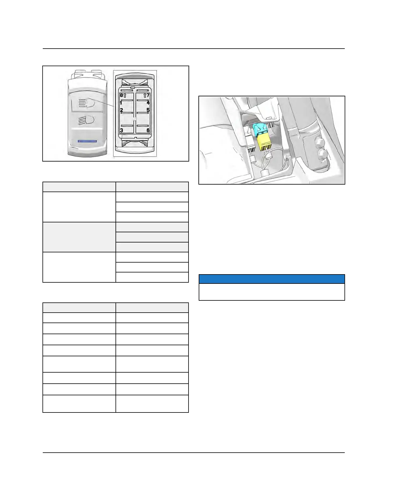
HEADLIGHT SWITCH
PIN CONTINUITY
SWITCH POSITION CONTINUITY BETWEEN
High
Pins 2 and 3
Pins 5 and 6
Pins 7 and 8
Low
Pins 2 and 3
Pins 4 and 5
Pins 7 and 8
Off
Pins 1 and 2
Pins 4 and 5
Pins 7 and 8
SWITCH FUNCTION
PIN FUNCTION
1
—
2
Jumper, Headlight Switch
3
Low Beam, Switch Out
4
Jumper, Headlight Switch
5
Lights, Headlight Switch
In
6
High Beam, Switch Out
7
Ground, Headlight Switch
8
Key Switch B+, Headlight
Switch Light
TESTING
1. Disconnect the headlight switch harness on the back
side of the dash by depressing the connector locks
and pulling on the connector. Do not pull on the
wiring.
2. Test between the 3 sets of outputs (OFF / LOW /
HIGH). If any of the tests fail, replace headlight switch
assembly.
• Move the switch to HIGH. There should be
continuity between switch pins 2 and 3; 5 and 6; 7
and 8.
• Move the switch to LOW. There should be
continuity between switch pins 2 and 3; 4 and 5; 7
and 8.
• Move the switch to OFF. There should be continuity
between switch pins 1 and 2; 4 and 5; 7 and 8.
NOTICE
Pins 7 and 8 provide power and ground to light the
switch lamp.
CHASSIS / BODY ELECTRICAL