Alteon Application Switch Operating System Application Guide
High Availability
522 Document ID: RDWR-ALOS-V2900_AG1302
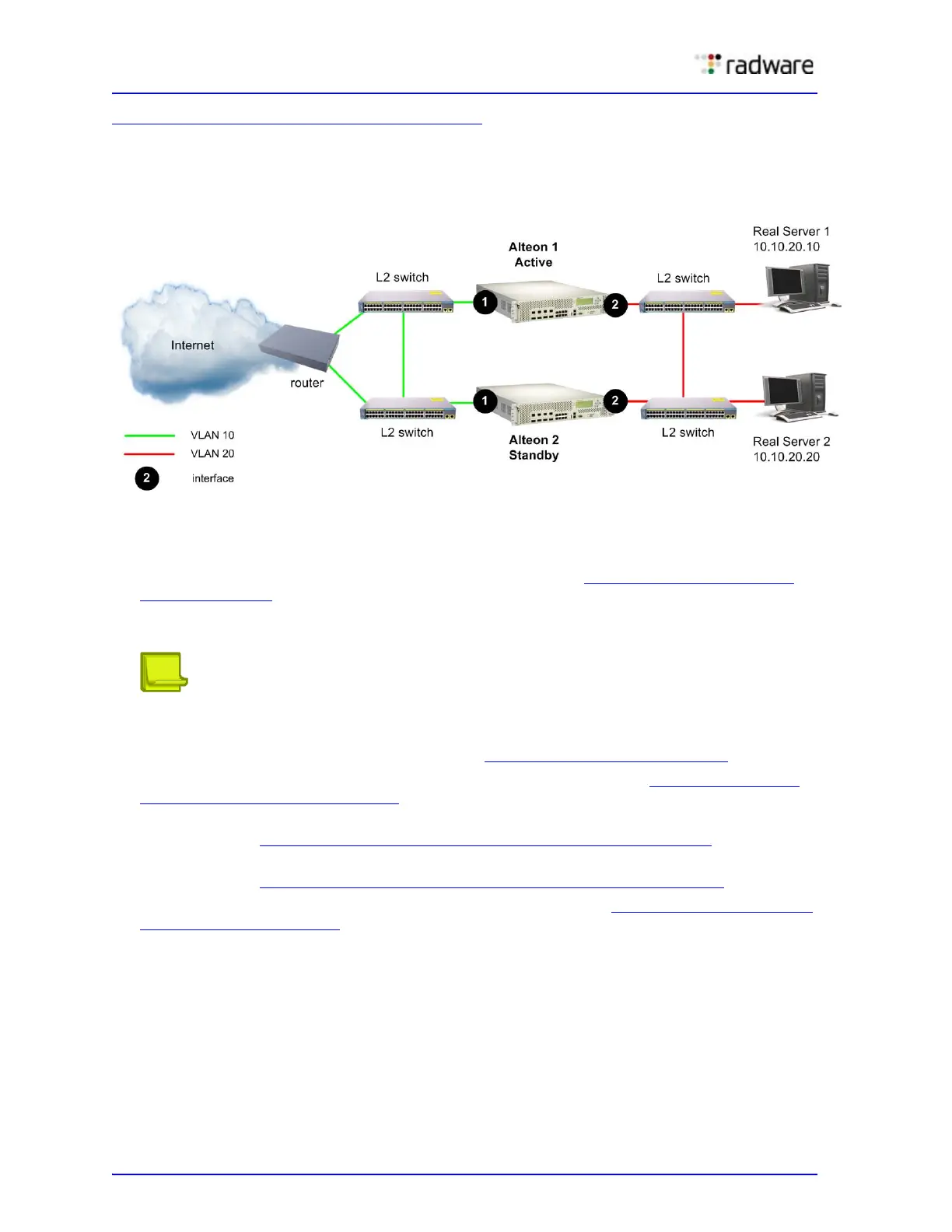
Figure 78 - Active-Standby Configuration, page 522 shows an active-standby configuration. In this
example, there are two VLANs, each with their own interface. The same two services are configured
on each Alteon.
Figure 78: Active-Standby Configuration
Configuring Active-Standby Redundancy
Perform the following steps on both the active and the standby Alteon:
1. Disable the Spanning Tree protocol. For more information, see To disable the Spanning Tree
protocol, page 523.
Using the Spanning Tree protocol or VLANs prevents Layer 2 loops. Radware recommends that
you use VLANs.
Note: The configuration does not require dedicated interswitch links (ISL), or hotstandby
settings on ports.
2. Enable IP forwarding. For more information, see To enable IP forwarding, page 523
.
3. Configure two interfaces, one for each VLAN. For more information, see To configure Layer 3
physical interface settings, page 523.
4. Configure virtual routers—one for each interface, and one for each service. For more
information, see To configure Layer 3 virtual router settings for VLANs, page 524
.
5. Define each service on a virtual server, and associate each service with a virtual router. For more
information, see To configure Layer 3 virtual router settings for services, page 526
.
6. Add all virtual routers to a VRRP group. For more information, see To configure VRRP grouping
for virtual routers, page 527.
Grouping virtual routers enables you to easily give them a common status (active or standby). A
virtual router can belong to one VRRP group only.