4-70 ECODRIVE03 DKC**.040, DKC**.100, DKC**.200 ECODRIVE03 Drive Controllers
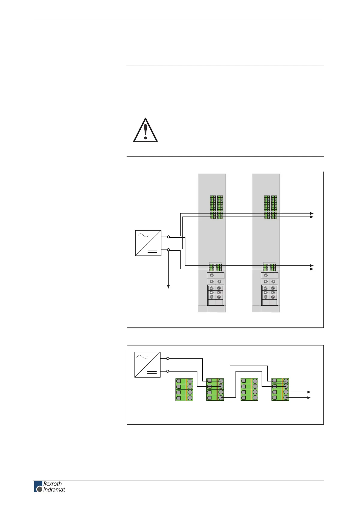
Voltage connection for brakes
Note: The motor holding brake is not supplied by the controller.
Given one voltage source for brake and control voltage, use
parallel leads from the voltage source. Note the voltage range
for the motor holding brake according to the motor projection.
CAUTION
Risk of damage!
The maximum allowed current load of the terminals
for the voltage supply of the brake and the control
voltage supply must also be observed in the case of
a short circuit.
Ap5126f1.fh7
123 4 5 6 7 8 9
123 4 5 6 7 8 9
123 4
123 4
11121314 1516 1718
567 8
123 4
123 4
567 8
123 4 5 6 7 8 9
123 4 5 6 7 8 9
123 4
123 4
11121314 1516 1718
567 8
123 4
123 4
567 8
DKC DKC
X1 X1
X6 X6
24V
to the central
ground
to additional
devices
Fig. 4-104: Shared voltage source for brakes and control voltage supply
Ap5140f1.fh7
24V
X6
123 4
567 8
X6
123 4
567 8
to additional
devices
Fig. 4-105: Looping through the brake supply
customerservice@hyperdynesystems.com | (479) 422-0390

 Loading...