4-76 ECODRIVE03 DKC**.040, DKC**.100, DKC**.200 ECODRIVE03 Drive Controllers
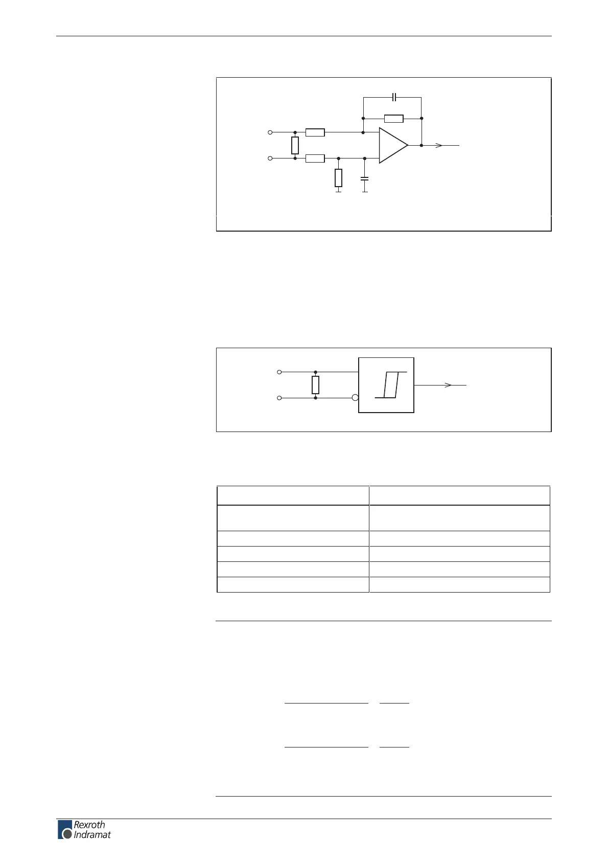
Input circuit for sine signals G2Sin+ (A+), G2Sin- (A-):
AP5299F1.FH7
R1
R4
R2
R3
-
+
E+
E-
C2
C1
R5
Schematics
R1: no data
R2: no data
R3: no data
R4: no data
R5: 120R
C1: no data
C2: no data
Fig. 4-114: Input circuit for sine signals
Input circuit for square-wave signals G2Sin+ (A+), G2Sin- (A-):
AP5300F1.FH7
E+
E-
R5
A
B
Schematics
R5: 120R
Fig. 4-115: Input circuit for square-wave signals
Features of the dierential input G2Sin+ (A+), G2Sin- (A-):
Input voltage
max. allowed amplitude encoder
signal (U
SSencoder signal
)
(1,0 + 0,2) Vss
tiB 21retrevnoc DA noitaulavE
zHk 002ycneuqerf timiL
R 021ecnatsiser tupnI
Resolution over a encoder cycle See the following note
Fig. 4-116: Features of the dierential input (Sine encoder)
Note: Resolution over a period under the assumption of the following
conditions:
• Dierential signal 1.0V
SS
• Reference voltage for the dierential signal 2.7 V
•
ignalSSencoders
SS
12
U
V2,1
2
cycle Encoder
resolution Position
•=
Example: If U
SSencoder signal
= 1 V
SS
6826V1
V2,1
2
yclec Encoder
resolution Position
SS
SS
12
=•=
=> see also rmware functional description "Optional encoder"
(Encoder 2)
G2Sin+ (A+), G2Sin- (A-):
Sine encoder:
customerservice@hyperdynesystems.com | (479) 422-0390

 Loading...