ECODRIVE03 Drive Controllers ECODRIVE03 DKC**.040, DKC**.100, DKC**.200 4-79
Allowed encoder cable lengths
Selecting wire cross sections
Note: The current consumption of the connected encoder systems
generates a voltage drop due to the resistively ( dependent
upon the wire cross sections and lengths) of the wire. This
reduces the signal at the encoder input.
To compensate the voltage drop, the DKC can inuence the
encoder power source. Using a voltage sensor, the available
voltage at the encoder is known.
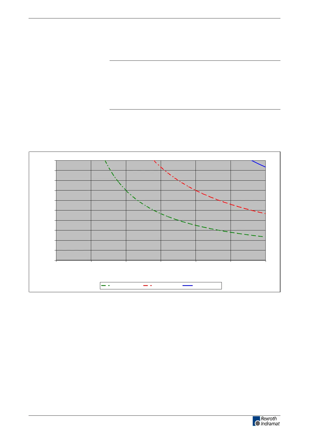
For a given wire length and encoder current consumption, a minimum
cross section becomes necessary. This relationship is illustrated
below.
1. With sensor connection in the encoder lead
0
5
10
15
20
25
30
35
40
45
50
0 0,05 0,1 0,15 0,2 0,25 0,3
I [A]
L [m]
A = 0,25 mm ² A = 0,5 mm ² A = 1,0 mm ²
L: cable length
I: current
A: wire cross sections
Fig. 4-120: With sensor connection
customerservice@hyperdynesystems.com | (479) 422-0390

 Loading...